
Optical communication systems including optical amplifiers an amplification methods

Inactive Publication Date: 2008-03-27
OPTIC153 LLC
View PDF26 Cites 11 Cited by
  • Summary
  • Abstract
  • Description
  • Claims
  • Application Information

AI Technical Summary

Benefits of technology

[0023] Continuing the present example, the erbium amplifier could be operated with a higher gain and lower noise figure at one end of the signal wavelength spectrum, whereas the Raman amplifier could be operated with a lower gain and higher noise figure at one end of the signal wavelength spectrum. The net effect would be a composite gain and noise figure that can be controlled across the entire signal wavelength spectrum to a desired shape.
[0027] In some instances the gain and noise figure profiles of various amplifiers do not vary in such a way as to readily allow for creating a desired composite gain and noise figure profile. In another aspect of the invention, the optical amplifiers can be used in combination with gain flattening filters, such as fiber Bragg gratings, and / or other components, i.e., “gain profile varying devices”, to vary the relationship between the gain profile and the noise figure profile of the amplifier. Varying the gain and noise figure relationship of the amplifier allows the composite gain and noise figure profiles to be more easily tailored to meet specific system design requirements.
[0031] The present invention provides optical amplifiers with improved performance over a signal channel wavelength range, and, hence, improved optical transmission system performance. These advantages and others will become apparent from the following detailed description.

Problems solved by technology

A limitation in multiple channel transmission systems, including WDM systems, is that the performance of signal channels being transmitted through the system can vary significantly over the wavelength range used to transmit signal channels through the system.
The exacerbation is due to different amplifiers having different performance characteristics, such as gain and noise figure over a signal channel wavelength range, which can negatively impact uniform performance over the wavelength range.
The varying degradation mechanisms can result in diminished system performance over at least a portion of the signal channel range.
Either of these operational modes is often less than desirable.
The former mode results can result in the added expense associated with premature regeneration of better performing signal channels to maintain uniform system performance.
The latter mode can place significant constraints on the network planning, provisioning, and operations, because signal channels must be matched to individual circuits based on the length of the circuit and the performance of the signal channel in a particular portion of the network.

Method used


Image

  • Optical communication systems including optical amplifiers an amplification methods
  • Optical communication systems including optical amplifiers an amplification methods
  • Optical communication systems including optical amplifiers an amplification methods

Examples


Embodiment Construction

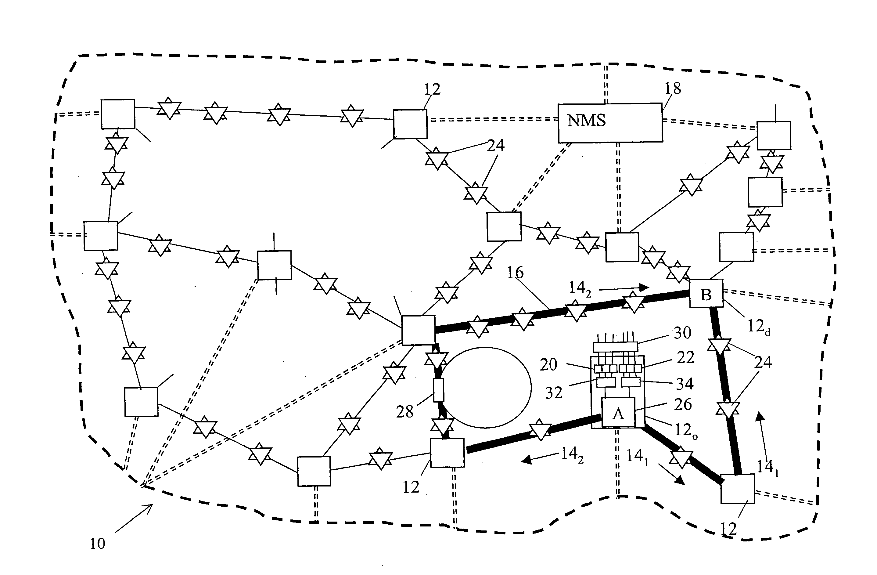
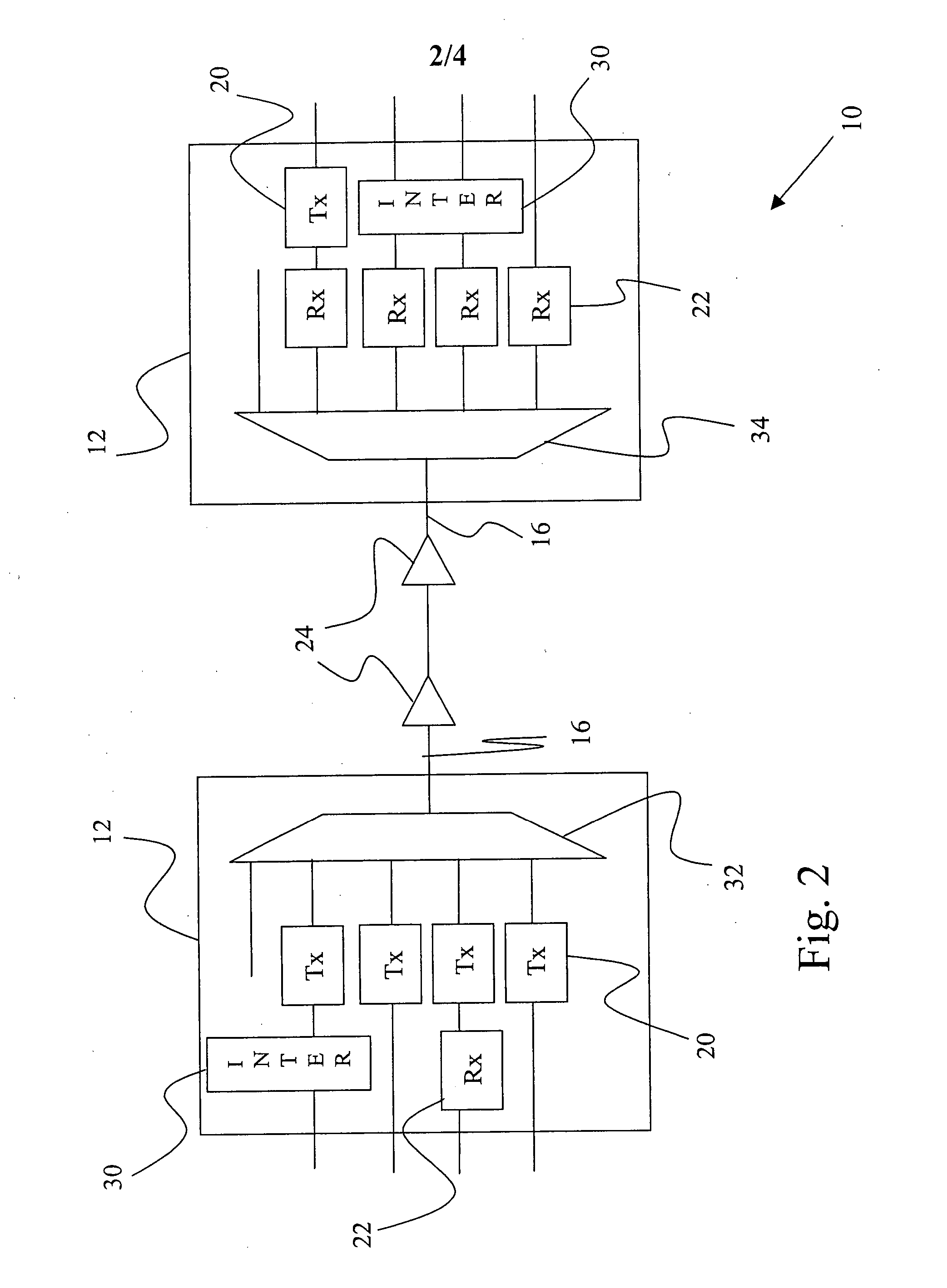
[0036]FIG. 1 illustrates an optical system 10, which includes a plurality of nodes 12 connected by optical communication paths 14. Advantages of the present invention can be realized with many system 10 configurations, topologies, and architectures. For example, an all optical network, one or more interconnected point to point optical links (FIG. 2), and combinations thereof can be configured in various topologies, i.e., rings, mesh, etc. to provide a desired network connectivity.

[0037] The system 10 can support one or more transmission schemes, such as space, time, polarization, code, wavelength and frequency division multiplexing, etc., singly or in combination within a network to provide communication between the nodes 12. The system 10 can include various types of transmission media 16 and be controlled by a network management system 18.

[0038] As shown in FIG. 1, optical processing nodes 12 generally can include one or more optical components, such as transmitters 20, receiver...


PUM


Abstract

Optical systems of the present invention include first and second optical amplifiers that are operated individually to provide gain profiles that do not conform with a desired composite, or overall or total, gain profile, e.g., substantially flat, but to produce a desired composite noise figure profile, e.g., substantially flat or otherwise, for the amplifiers. Generally, the desired composite noise figure profile is produced, while attempting to minimize the deviation of the composite gain profile from the desired composite gain profile.

Description

CROSS-REFERENCE TO RELATED APPLICATIONS [0001] This application claims priority from U.S. Provisional Patent Application No. 60 / 546,108, filed Feb. 19, 2004, which is incorporated herein by reference.STATEMENT REGARDING FEDERALLY SPONSORED RESEARCH OR DEVELOPMENT [0002] Not Applicable BACKGROUND OF THE INVENTION [0003] The present invention is directed generally to optical systems. More particularly, the invention relates to optical systems including optical amplifiers and methods for use therein. [0004] The continued growth in traditional communications systems and the emergence of the Internet as a means for accessing and communicating information has accelerated demand for high capacity communications networks. Telecommunications service providers, in particular, have looked to wavelength division multiplexed (“WDM”) transmission systems to increase the capacity of their optical fiber networks to meet the increasing demand. [0005] In WDM transmission systems, distinct wavelength ...

Claims


Application Information

Patent Timeline
IPC IPC(8): H04B10/12H01S3/091
CPCH04B10/2941H04B10/2933
Inventor STEPHENS, THOMAS
Owner OPTIC153 LLC
Learn More