
Adjuster systems for continuous variable transmissions

a technology of continuous variable transmission and adjuster system, which is applied in the direction of gearing, gearing elements, hoisting equipment, etc., can solve the problems of large normal forces, cvts that depend on friction to transmit torque, and cvts that cannot be changed, so as to reduce transition flexing, eliminate or eliminate the effect of cvts

Inactive Publication Date: 2006-11-09
TAY ARMIN SEBASTIAN
View PDF2 Cites 44 Cited by
  • Summary
  • Abstract
  • Description
  • Claims
  • Application Information

AI Technical Summary

Benefits of technology

[0007] The purpose of this application is to improve the performance of CVTs that suffer from either or both transition flexing and a limited duration at which the transmission ratio can be changed, by eliminating or significantly reducing transition flexing and by substantially increasing the duration at which the transmission ratio of those CVTs can be changed. Although the emphasis is in improving the performance of the CVTs of U.S. Pat. No. 6,656,070, other type of CVTs that

Problems solved by technology

The main disadvantage of a V-belt CVT, a cone CVT and a toroidal CVT is that they depend on friction to transmit torque.
And generating these large normal forces reduces the efficiency of those CVTs.
And here sliding a torque transmitting surface relative to another normally requires a large actuating force and can cause a lot of wear in the torque transmitting surfaces.
Although a ratcheting CVT does not have to depend on friction to transmit torque, because of its ratcheting action, its operation is inefficient and unsmooth.
Excessive cycles of transition flexing can reduce the life of a CVT.

Method used


Image

  • Adjuster systems for continuous variable transmissions
  • Adjuster systems for continuous variable transmissions
  • Adjuster systems for continuous variable transmissions

Examples


Embodiment Construction

—PREFERRED EMBODIMENTS

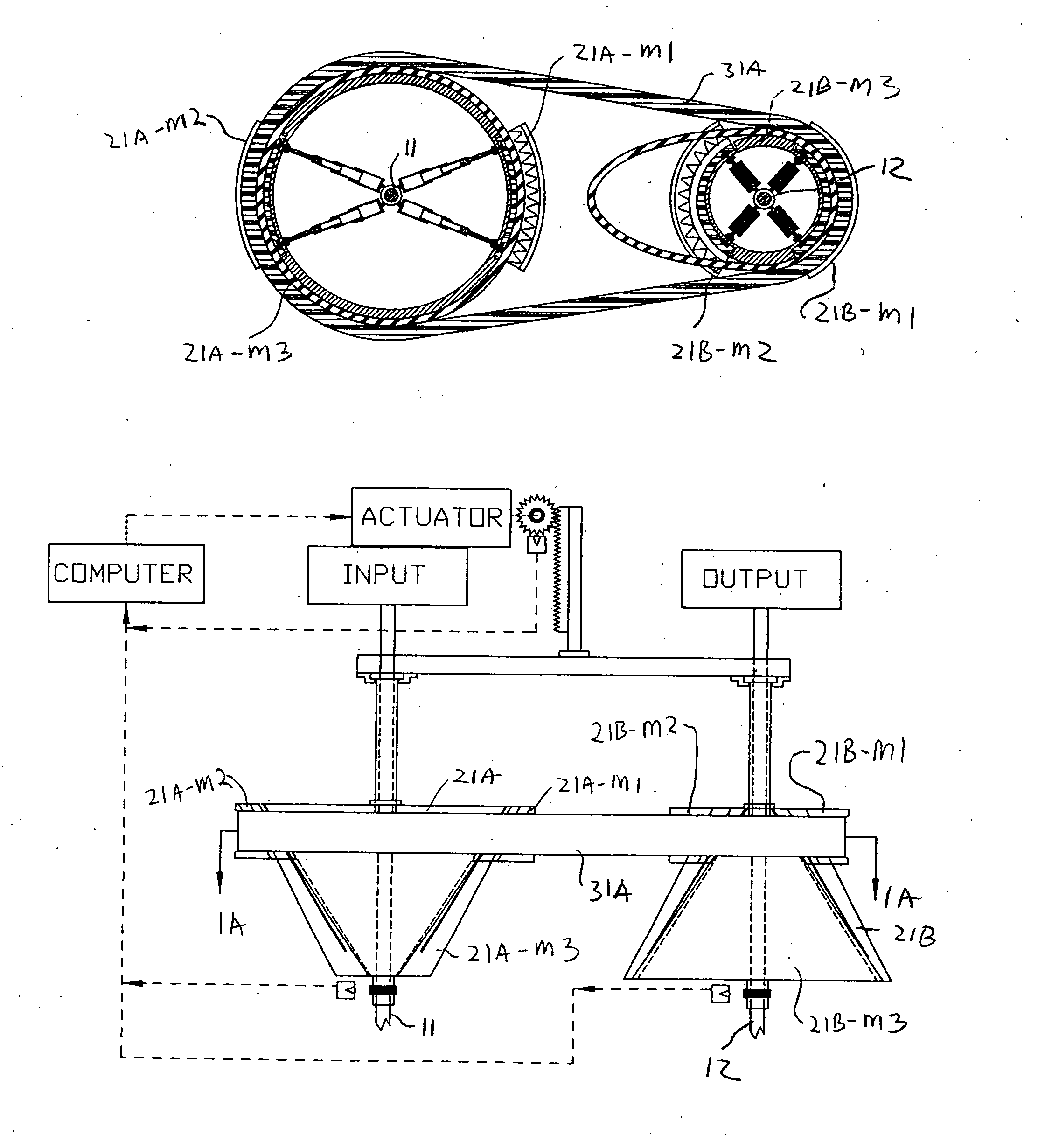
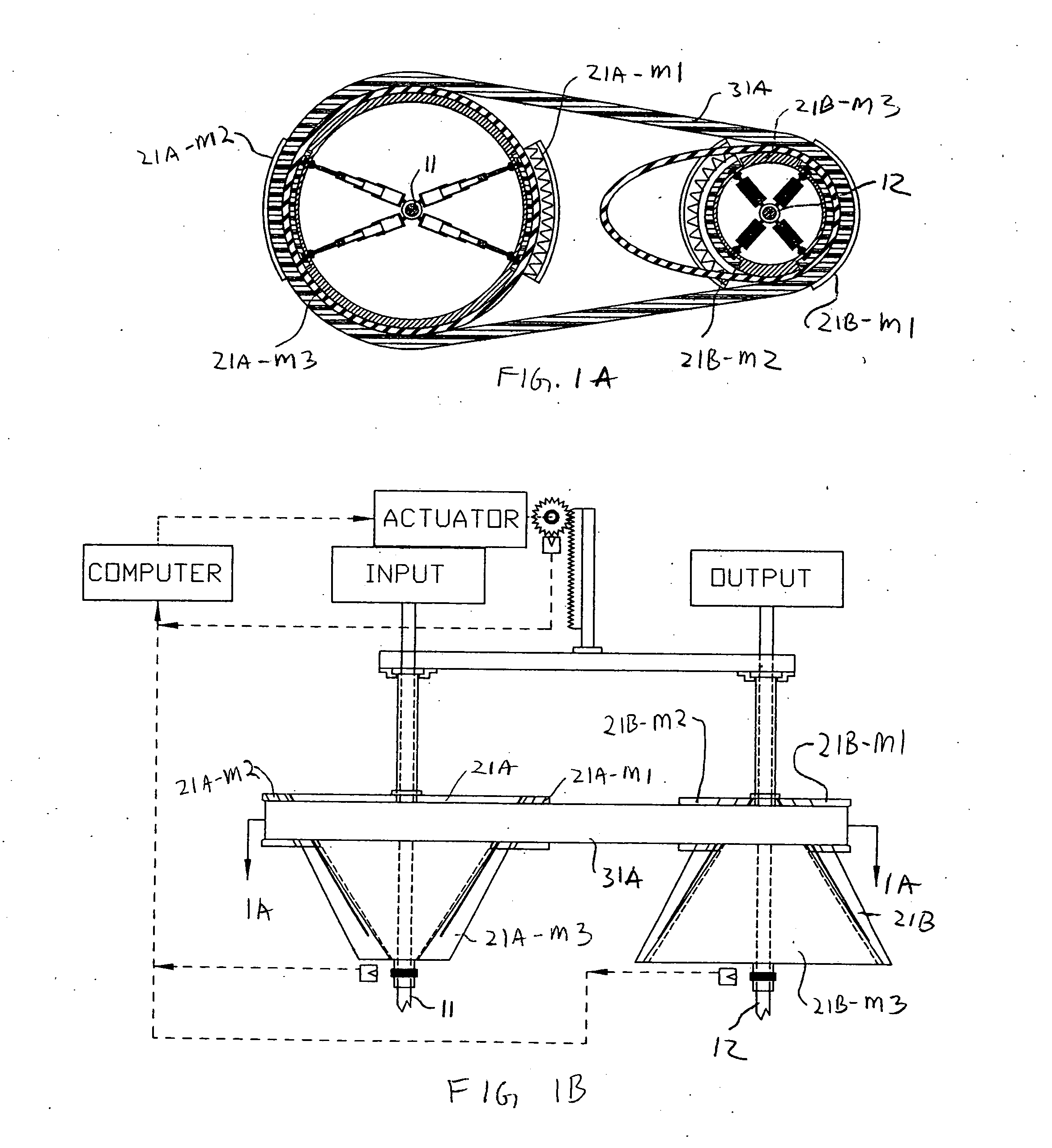
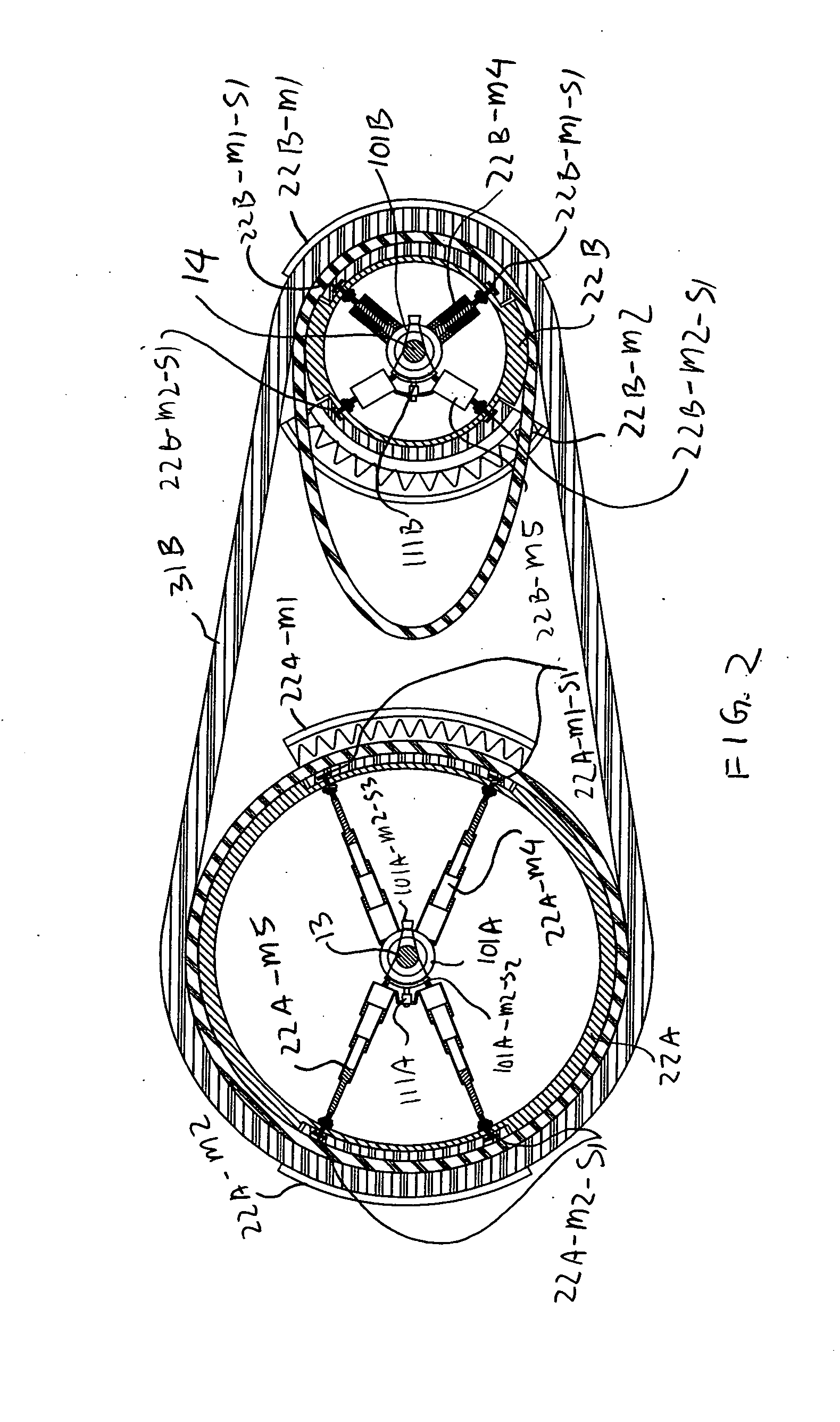
[0801] In this section, first the preferred embodiments of adjuster systems for CVT 1 and CVT 2 of U.S. Pat. No. 6,656,070 will be described. Then, an electrical adjuster that can be used in an adjuster system is described.

[0802] The purpose of this invention is to introduce adjuster systems, hence specific details concerning the CVTs that can benefit from them, such as the method of attaching a torque transmitting member to a cone assembly, and the method of changing the axial position of the torque transmitting members, are not described in this section. These details are described in U.S. Pat. No. 6,656,070.

[0803] Also in case no specific method of fixing one part to another is described, then the method of gluing one part to another can be used. Although more sophisticated methods might be preferable, having to explain these methods would complicate the description of the invention without helping in describing the essence of the invention. Also in case n...


PUM


Abstract

Rotational position adjuster systems that can increase the performance of CVTs that suffer from either or both transition flexing and a limited duration at which the transmission ratio can be changed by providing proper rotational adjustment.

Description

CROSS REFERENCE TO RELATED APPLICATIONS [0001] This invention is a Continuation-in-part (CIP) of U.S. patent application Ser. No. 11 / 039,297, which was filed on Jan. 20, 2005. In addition, this invention is entitled to the benefit of Provisional Patent Application (PPA) Ser. No. 60 / 696,588 filed on Jul. 5, 2005, PPA Ser. No. 60 / 700,847 filed on Jul. 19, 2005, PPA Ser. No. 60 / 724,098 filed on Oct. 6, 2005, PPA Ser. No. 60 / 729,822 filed on Oct. 25, 2005, PPA Ser. No. 60 / 773,916 filed on Feb. 16, 2006, PPA Ser. No. 60 / 795,528 filed on Apr. 27, 2006.BACKGROUND [0002] 1. Field of Invention [0003] This invention relates to rotational position adjuster systems that can increase the performance of CVTs that suffer from either or both transition flexing and a limited duration at which the transmission ratio can be changed. [0004] 2. Description of Prior Art [0005] Most mechanical CVTs available today are either a V-belt CVT, a cone CVT, a toroidal CVT, or a ratcheting CVT. A V-belt CVT basic...

Claims


Application Information

Patent Timeline
IPC IPC(8): F16H59/00F16H9/00F16H55/56
CPCF16H9/08F16H63/067F16H55/54F16H9/14
Inventor TAY, ARMIN SEBASTIAN
Owner TAY ARMIN SEBASTIAN
Learn More