
Method for auto-calibration of a tool in a single point turning machine used for manufacturing in particular ophthalmic lenses

a single-point diamond turning and auto-calibration technology, applied in the direction of optical surface grinding machines, manufacturing tools, instruments, etc., can solve the problems of variable accuracy and repeatability, method does not lend itself to identifying the center and/or radius of the tool tip

Active Publication Date: 2006-11-09
SATISLOH GMBH
View PDF14 Cites 27 Cited by
  • Summary
  • Abstract
  • Description
  • Claims
  • Application Information

AI Technical Summary

Benefits of technology

[0021] In this way a reliable and economic two-dimensional (2D) tool / machine calibration is performed. A particular advantage of this method consists in the fact that, due to the test piece geometry cut and probed, the geometry of the cutting edge on both sides of the center of the cutting edge is taken into consideration in the calibration of the machine. This is of particular importance to the calibration if (optical) surfaces shall be cut that have prism at the center of rotation in which case the cutting edge comes into cutting engagement with the surface to be cut on both sides of center of the cutting edge.
[0022] The step of cutting the test piece may include cutting a circular groove in the face of the test piece, as an advantageously simple test piece geometry. Further, the step of probing the cut geometry of the test piece can include capturing probe data along a straight line starting on one side of the test piece, and extending through to the other side of the test piece while passing through or close by the axis of work rotation, as an easy-to-perform probing procedure. When probing the cut geometry of the test piece the probe data is preferably captured in a continuous fashion, i.e. the probe is first brought into contact with the test piece and the probe contact with the test piece is then maintained using a low but constant force, while moving the test piece relative to the probe or vice versa.
[0030] In this way a reliable and economic three-dimensional (3D) tool / machine calibration is performed. A particular advantage of this method consists in the fact that, with the test piece geometry cut and probed, significantly more information about tool calibration to center can be obtained to compensate for even errors in the Z-direction.
[0031] In this instance the step of cutting the test piece may include cutting a geometry which is axisymmetric along two axes in the X-Z plane on the face of the test piece. Moreover, the step of probing the cut geometry of the test piece can include capturing probe data at a given radial distance from the axis of work rotation while rotating the test piece about the axis of work rotation, preferably over an angle of 360 degrees, as an easy-to-perform probing procedure.

Problems solved by technology

The disadvantages with this first method are those of accuracy and repeatability being variable, and speed being slow and unpredictable.
The method does not lend itself to identifying the center and / or radius of the tool tip.
Also, another problem with this first method is possible damage to the tool during the scribing part of the procedure.
The disadvantages with this approach are those of speed, and operator involvement.
Also, unless many hundreds of points along the tool edge are captured at sub-micron accuracies, which is not practical at all, the method cannot automatically calibrate for tool tip circularity errors.
Another problem with this approach is identified when the tool tip has a “blunt edge”.
In this case, measuring the height of the tool using a focus point on the rake face does not properly identify the height of the true point at which the tool cuts; and accurately focussing at the very edge is quite difficult.
These methods, however, have the same disadvantages as described above.
However, none of these methods calibrate for tool tip radius, or circularity.
In addition, like was the situation with the second method, tool height cannot be accurately determined if the tool has a blunt edge since only the rake face is mechanically probed.
This procedure has the disadvantage that it is slow and time consuming to apply, due to the fact that it needs to be repeated for each part geometry to be cut.
Also, this method only maps errors on one side of center, meaning it does not consider the possibility of cutting parts with prism, i.e. parts having a surface which is tilted with respect to the axis of rotation.
Thirdly it is not a calibration method which lends itself to a general tool / machine calibration including Z-height errors.
Summarily, the current state of the art uses methods which are based on manual, operator dependent procedures, and are therefore prone to errors, provide for partial tool calibration only and / or are slow in their implementation and practice.

Method used


Image

  • Method for auto-calibration of a tool in a single point turning machine used for manufacturing in particular ophthalmic lenses
  • Method for auto-calibration of a tool in a single point turning machine used for manufacturing in particular ophthalmic lenses
  • Method for auto-calibration of a tool in a single point turning machine used for manufacturing in particular ophthalmic lenses

Examples


Embodiment Construction

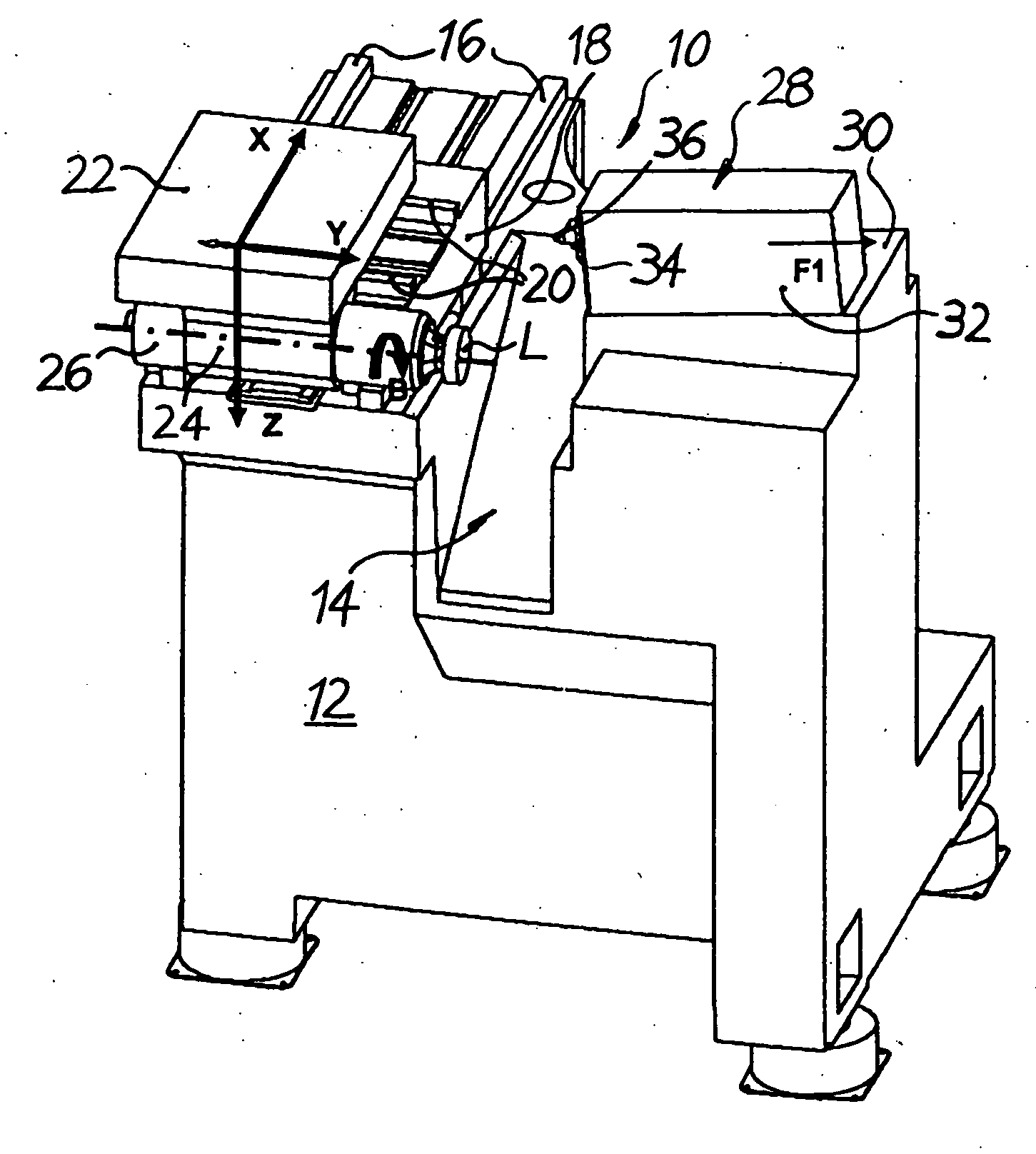
[0054]FIG. 1 shows a CNC-controlled single point turning machine 10 in particular for surface machining of plastic spectacle lenses L. The single point turning machine 10 has a frame 12 defining a machining area 14. On the left of the machining area 14 in FIG. 1 two guide rails 16 extending horizontally and parallel to each other are attached to an upper surface of the frame 12. An X-carriage 18 displaceable horizontally in both directions of an X-axis by assigned CNC drive and control elements (not shown) is mounted slidably on the two guide rails 16. Two further guide rails 20 extending horizontally, parallel to each other and perpendicular to the guide rails 16 are attached to an upper surface of the X-carriage 18. In a cross slide table arrangement a Y-carriage 22 displaceable horizontally in both directions of a Y-axis by assigned CNC drive and control elements (likewise not shown) is mounted slidably on the two further guide rails 20. Attached to a lower surface of the Y-carri...


PUM

PropertyMeasurementUnit
Angleaaaaaaaaaa
Lengthaaaaaaaaaa
Widthaaaaaaaaaa

Abstract

A method for auto-calibration of at least one tool (36) in a single point turning machine (10) used for manufacturing in particular ophthalmic lenses (L) is proposed, in which a test piece of special, predetermined geometry is cut with the tool and then probed to obtain probe data. The method subsequently uses the probe data to mathematically and deterministically identify the necessary tool / machine calibration corrections in two directions (X, Y) and three directions (X, Y, Z), respectively, of the machine. Finally these corrections can be applied numerically to all controllable and / or adjustable axes (B, F1, X, Y) of the machine in order to achieve a (global) tool / machine calibration applicable to all work pieces within the machines operating range. As a result two-dimensional (2D) tool / machine calibration and three-dimensional (3D) tool / machine calibration, respectively, can be performed in a reliable and economic manner.

Description

FIELD OF THE INVENTION [0001] The present invention relates to a method for auto-calibration of a tool in a single point diamond turning (SPDT) machine used for manufacturing in particular ophthalmic lenses. Such machine is disclosed in, e.g., document WO-A-02 / 06005 by the same inventors. [0002] SPDT is a well known method for generating non-rotationally symmetrical surfaces commonly used for ophthalmic eyeglass lenses. The surfaces are typically of toric or toroidal shape, or of completely freeform shape, such as those used in progressive addition lenses (PALs) One common problem encountered in these SPDT machines is a small, but unacceptable error at the center of rotation of the lens. These errors are typically caused by errors of calibration, causing the tool to not quite reach, or stop within acceptable tolerances from the center of rotation. BACKGROUND OF THE INVENTION [0003] In the prior art there is no lack of proposals as to how the tool / machine calibration may be realized....

Claims


Application Information

Patent Timeline
IPC IPC(8): G06F19/00B24B49/00
CPCB24B13/005B24B13/01B24D3/342B24B49/00B24B51/00B24B13/06
Inventor MCPHERSON, EDWARDSAVOIE, MARC
Owner SATISLOH GMBH
Features
  • Generate Ideas
  • Intellectual Property
  • Life Sciences
  • Materials
  • Tech Scout
  • Unparalleled Data Quality
  • Higher Quality Content
  • 60% Fewer Hallucinations
Learn More