
Measuring mud flow velocity using pulsed neutrons

a technology of pulsed neutrons and flow velocity, which is applied in the field of measuring mud flow velocity using pulsed neutrons, can solve the problems of inability to deploy while drilling, adverse effects of various lwd or mwd tools used in formation logging, and inability to detect and detect the flow velocity of mud,

Inactive Publication Date: 2006-11-16
SCHLUMBERGER TECH CORP
View PDF5 Cites 11 Cited by
  • Summary
  • Abstract
  • Description
  • Claims
  • Application Information

AI Technical Summary

Benefits of technology

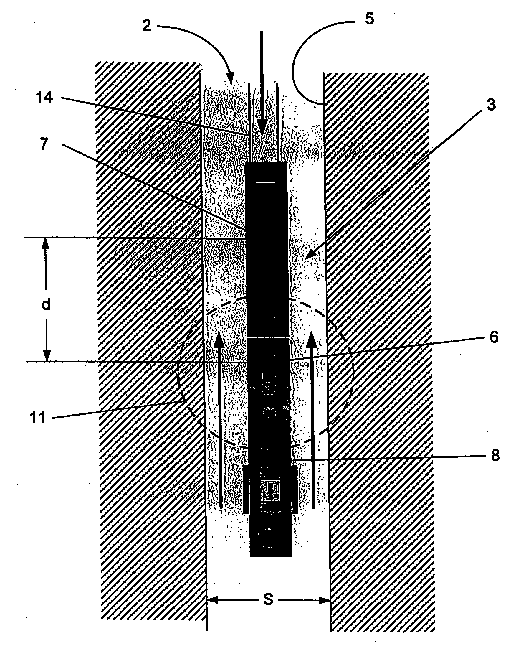
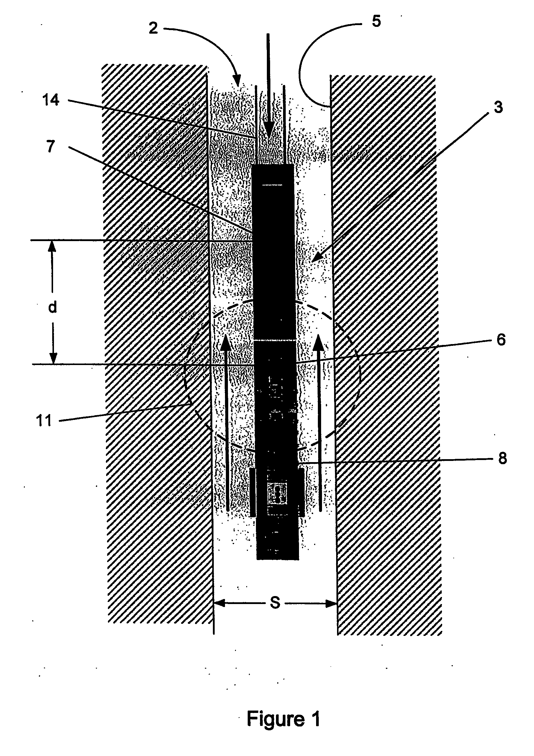
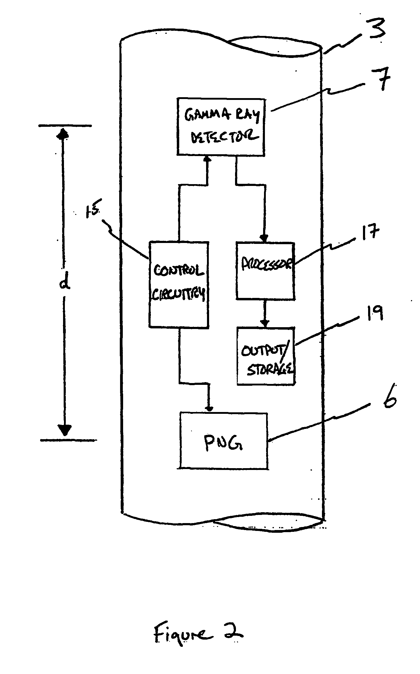
[0009] Another aspect, of the invention relates to a tool for determining downhole parameters. A tool for determining a downhole parameter in a drilling environment is a tool adapted to be placed in a drill string, wherein the tool has a pulsed neutron generator (6) and a gamma ray detector (7) separated along a drill string axis thereof by a distance d. The tool further includes: control circuitry operable to turn off the pulsed neutron generator (6) for a time sufficient to create an unactivated slug of drilling fluid flowing past the tool; and processing means (17), responsive to the gamma ray detector (7), for determining when th

Problems solved by technology

Modern oil and gas explorations typically use LWD or MWD tools, instead of wireline tools, for formation logging due to the saving in time and costs.
However, various LWD or MWD tools used in formation logging are adversely affected by the presence of drilling fluids (muds) and their sensitivities are typically compromised by tool “stand offs,” i.e., the distances from tools (or sensors) to the borehole wall.
However, most of these tools are useful only as wireline tools; they cannot be deployed while drilling.
Furthermore, large quantities of drilling fluids are pumped through the drill strings into the boreholes while the boreholes are being drilled.
The higher hydraulic pressure of the drilling fluids may result in a substantial loss of fluid into the formation when a permeable and low pressure zone of the earth formation is encountered.
Such a process does not match well with the LWD environment or with neutron tools, where the PNG remains activated most of the time.

Method used


Image

  • Measuring mud flow velocity using pulsed neutrons
  • Measuring mud flow velocity using pulsed neutrons
  • Measuring mud flow velocity using pulsed neutrons

Examples


Embodiment Construction

[0015] The invention relates to methods and apparatus for determining flow velocities of drilling fluids (“muds”) in boreholes. The invention, advantageously, may be used while drilling a borehole. The fluid velocity permits the calculation of other downhole parameters, such as the borehole diameter and the volumetric flow rate of the mud.

[0016] In some embodiments, the invention relies on the activation of oxygen in the drilling mud. In the activation process, oxygen atoms in the drilling mud are transformed from stable atoms into radioactive atoms by the bombardment of neutrons. When an oxygen-16 atom absorbs a neutron (neutron capture), it may emit a proton to produce a radioactive nitrogen-16 atom. Nitrogen-16, with a half-life of about 7.1 seconds, decays to oxygen-16 by emitting a beta particle. The oxygen-16 that results from the beta decay of nitrogen-16 is in an excited state, and it releases the excitation energy by gamma ray emission. The gamma ray emission may be detect...


PUM


Abstract

The invention relates to methods and apparatus for determining downhole mud flow rates and other downhole parameters. A method for determining a downhole parameter includes operating a pulsed neutron generator (6), pulsing the pulsed neutron generator (6) off, detecting a substantially unactivated drilling fluid slug at a known distance (d) from the pulsed neutron generator (6), and determining a time-of-flight (t) for the unactivated drilling fluid slug to travel from the pulsed neutron generator (6) to a detection point.

Description

BACKGROUND OF INVENTION [0001] When drilling a borehole through a geologic formation, it is important to know the downhole conditions to ensure that the drill bit is operating correctly. These conditions include, among others, the diameter of the borehole and, therefore, the volume of the drilling fluid at any given point. In addition, the formation properties are measured to predict the presence of oil or gas. Formation properties may be logged with wireline tools, logging while drilling (LWD) tools, or measurement while drilling (MWD) tools. Modern oil and gas explorations typically use LWD or MWD tools, instead of wireline tools, for formation logging due to the saving in time and costs. [0002] Various LWD and MWD tools are in use for measuring borehole or formation properties. For example, LWD neutron or gamma spectroscopy logs are used to provide lithology, formation porosity, and formation density information. Neutron / gamma spectroscopy is often performed by sending a pulse of...

Claims


Application Information

Patent Timeline
IPC IPC(8): G01V5/12E21B47/00E21B47/10E21B47/08E21B49/08E21B47/11G01V5/10
CPCE21B47/0003E21B47/1015E21B47/082E21B47/003E21B47/085E21B47/11E21B47/10
Inventor WRAIGHT, PETER
Owner SCHLUMBERGER TECH CORP
Learn More