Ratchet wrench and method of assembling the same

a technology of ratchet wrenches and ratchets, which is applied in the direction of wrenches, power driven tools, screwdrivers, etc., can solve the problems of torque not increasing, and torque applied to the shank b>22/b> is decreased, so as to reduce the number of working hours, the problem of torque not being applied at the start of the operation, and the effect of constant friction

Inactive Publication Date: 2006-11-16
KEI TEII ESU
View PDF5 Cites 7 Cited by
  • Summary
  • Abstract
  • Description
  • Claims
  • Application Information

AI Technical Summary

Benefits of technology

[0020] The shank assembly as the one assembly is formed by attaching the spring for imparting the friction to the shank, the guide member for protecting the spring, and the washer to the shank with the hold means. The pressing force of the spring acts not on the outside of the shank assembly, but only on the shank of the shank assembly and the hold means. Therefore, the pressing force of the spring does not act on the pair of annular hold portions, and the force in the direction in which the distance between the pair of annular hold portions is outwardly increased is not applied to them unlike the conventional art. The pressing force of the spring is received inside the shank assembly, and it does not have an influence on the outside of the shank assembly. Therefore, the friction applied to the shank is kept constant, and the problem that the torque is not applied at the start of the operation can be eliminated.
[0021] The shank assembly is inserted from the central space of one of the annular hold portions toward the other annular hold portion, and the shank assembly is abutted on and held by the inner wall of the other annular hold portion. Then, the snap ring is attached to one of the annular hold portions to obstruct the drop-out of the shank assembly from the central space thereof. Thus, since the assembly of the ratchet wrench is such a simple work that the shank assembly is inserted and the snap ring is attached to one of the annular hold portions, the working hours can be shortened to achieve cost down.

Problems solved by technology

Since the forces in the opposite directions are applied to the first annular hold portion 12a and the second annular hold portion 12b by the disc spring 44 respectively, a distance between the first annular hold portion 12a and the second annular hold portion 12b is increased by long-term use, which results in a drawback that the friction applied to the shank 22 is decreased.
However, in the ratchet wrench in which the sandwiching means for preventing the outward increase in distance between the pair of annular hold portions 12a and 12b is included in the outsides of the pair of annular hold portions 12a and 12b, the friction applied to the shank 22 is excessively increased, which causes the drawback that a torque is not increased due to resistance at the start of the operation.
Thus, in the ratchet wrench including the means for preventing the outward increase in distance between the pair of annular hold portions 12a and 12b, there is the drawback that working efficiency is worsened because the torque is not increased at the start of the operation.

Method used


Image

  • Ratchet wrench and method of assembling the same
  • Ratchet wrench and method of assembling the same
  • Ratchet wrench and method of assembling the same

Examples


first embodiment

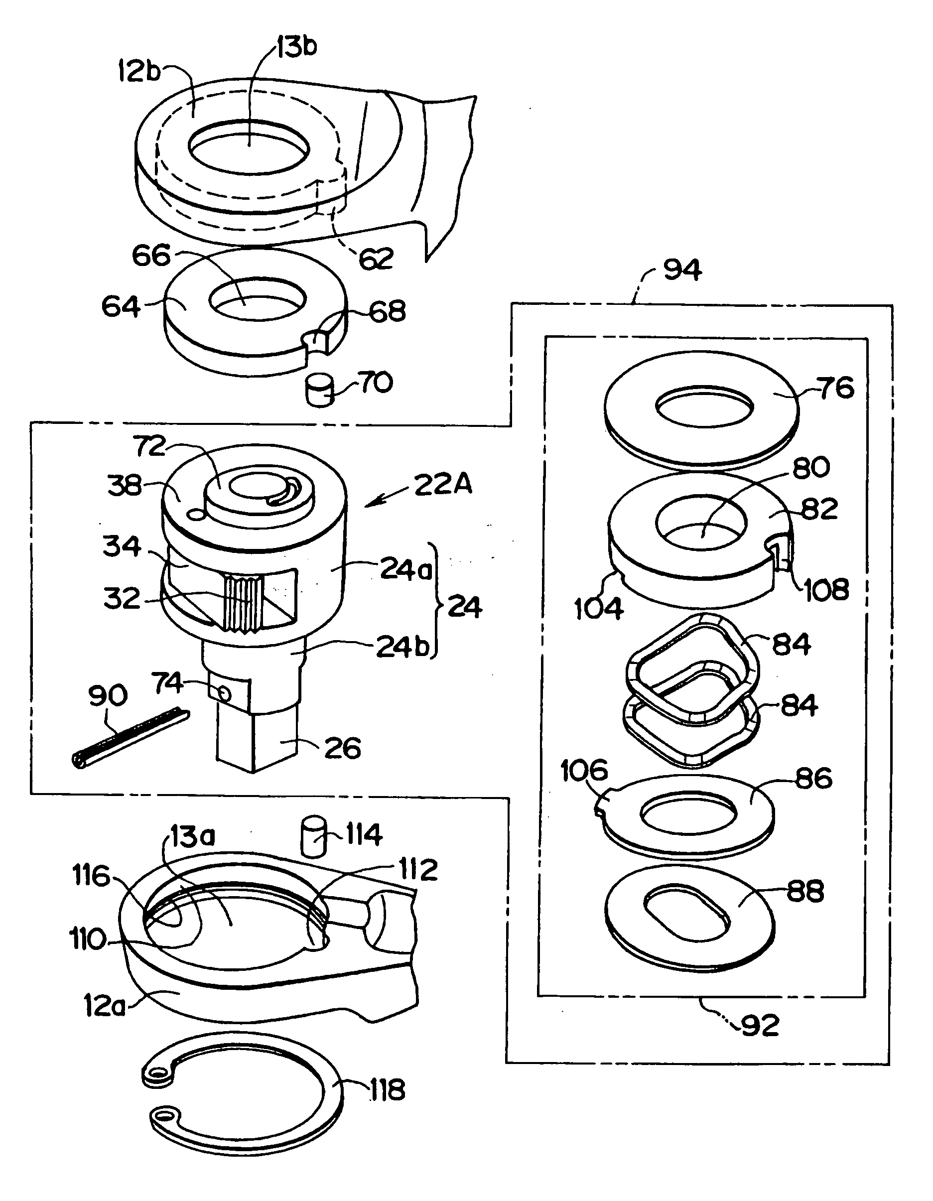
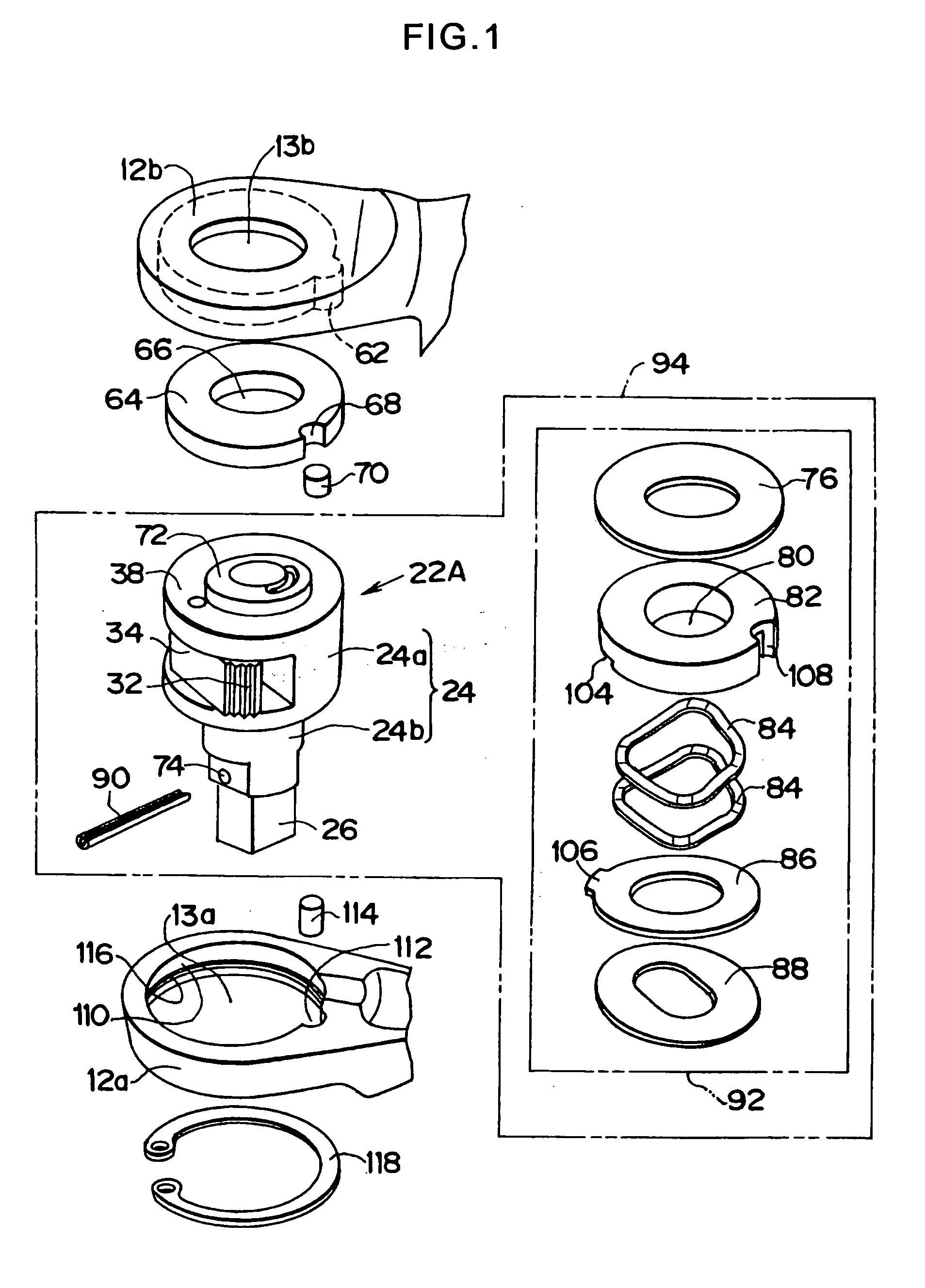
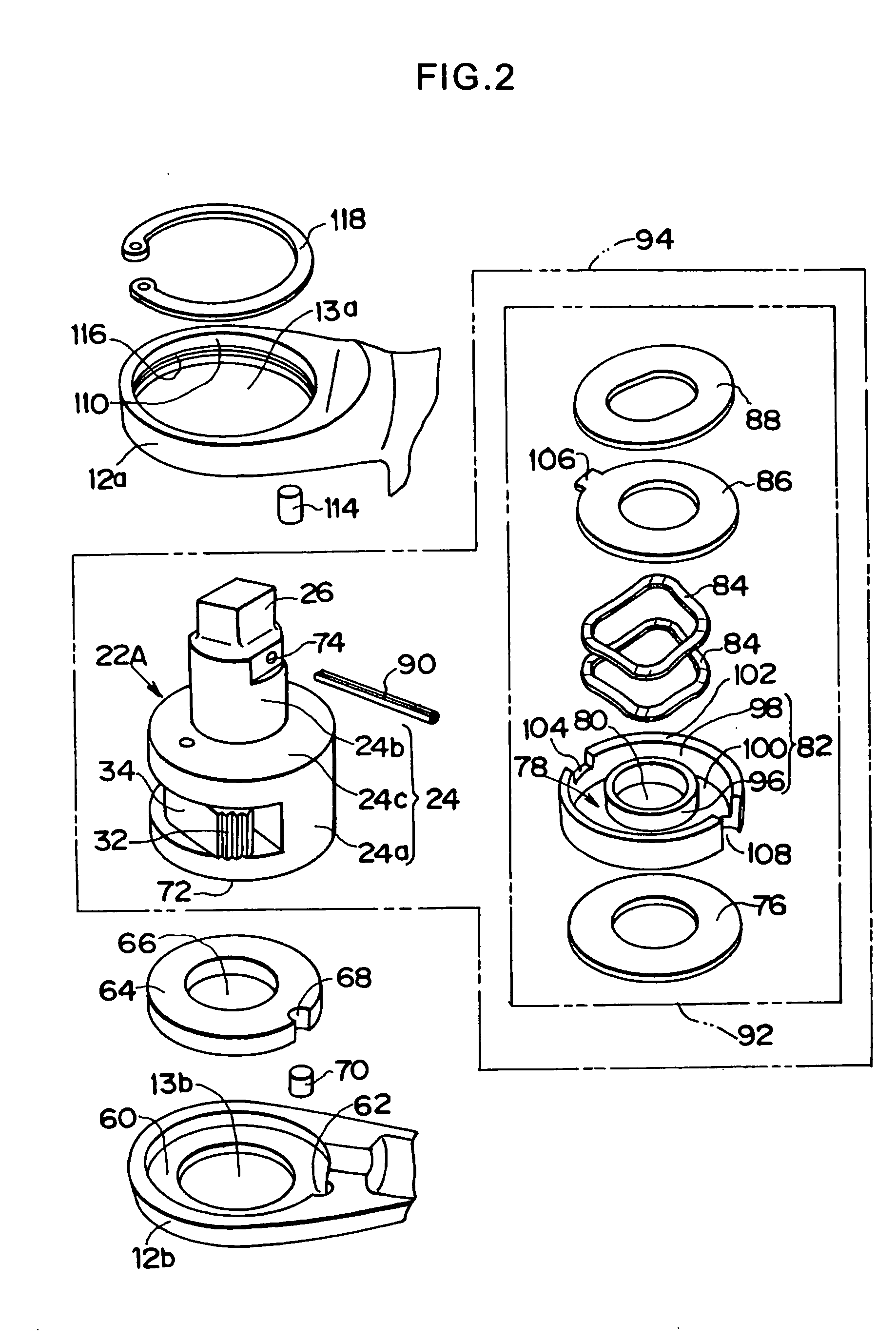
[0080]FIG. 1 is an exploded perspective view of a main part of the ratchet wrench according to the invention, FIG. 2 is an exploded perspective view when viewed from an opposite side of FIG. 1, FIG. 3 is a main-part sectional view showing a state in which the ratchet wrench of FIG. 1 and FIG. 2 is assembled, and FIG. 4 is a sectional view taken on line A-A of FIG. 3. In FIGS. 1 to 4, the same components as FIGS. 12 to 14 are designated by the same reference numerals. In a first embodiment, as-prepared material to which heat treatment such as quenching and annealing is not performed is used as a housing 10 including a first annular hold portion 12a and a second annular hold portion 12b. A first central space 13a is formed in the center of the first annular hold portion 12a, and a second central space 13b is formed in the center of the second annular hold portion 12b. An annular recess portion 60 is formed in an inner wall of the second annular hold portion 12b, and a substantially-se...

second embodiment

[0097] A second embodiment of the invention will be described below with reference to FIGS. 5 and 6.

[0098] In FIGS. 5 and 6, the same components as that shown in FIGS. 1 to 4 are designated by the same reference numerals. In the second embodiment, the material to which the heat treatment such as quenching and annealing is performed is used as the housing 10 including the first annular hold portion 12a and the second annular hold portion 12b. Since the material to which the heat treatment is performed is used as the first annular hold portion 12a and the second annular hold portion 12b, the upper surface 38 of a shank 22B may be brought into direct contact with the second annular hold portion 12b. Therefore, the second guide bush 64 used in the first embodiment will be omitted. Since the second guide bush 64 is omitted, in the shank 22B, a height of the base portion 24 is increased higher than a height of the base portion 24 of the shank 22A in order to fit to the distance between t...

third embodiment

[0100] A third embodiment of the invention will be described below with reference to FIGS. 7 to 9. In FIGS. 7 to 9, the same components as that shown in FIGS. 1 to 4 are designated by the same reference numerals. In the third embodiment, similarly to the first embodiment, the as-prepared material to which the heat treatment is not performed is used as the housing 10 including the first annular hold portion 12a and the second annular hold portion 12b. The same shank 22A as the first embodiment is used for the shank assembly 94. In the third embodiment, the shank assembly 94 is inserted from the central space 13b side of the second annular hold portion 12b toward the first annular hold portion 12a side with the engagement portion 26 in the lead.

[0101] As shown in FIG. 7, an annular recess portion 120 is formed in the inner wall of the first annular hold portion 12a, and a substantially-semi-cylindrical fitting recess portion 122 is formed at one point on the rim of the recess portion...


PUM


Abstract

The invention provides a ratchet wrench which can secure constant friction applied to a shank to generate a desired torque from start of an operation irrespective of an outward increase in distance between a pair of annular hold portions.
A frictional force generation means 92 including a first guide bush 82 and a disc spring 44 is attached to a shank 22A with a locking pin 90 to form a shank assembly 94 as an assembly. Spring force of the disc spring 44 acts not on the outside of the shank assembly 94, but only on the inside thereof. The shank assembly 94 is inserted from a central space 13a of a first annular hold portion 12a toward a second annular hold portion 12b, and the shank 22A is held by an inner wall of the second annular hold portion 12b. In the back side on which the shank assembly 94 is inserted, the drop-out of the shank assembly 94 from the central space 13a side of the first annular hold portion 12a to the outside is prevented by a snap ring 118 attached to a groove 116 of the first annular hold portion 12a.

Description

TECHNICAL FIELD [0001] The present invention relates to a ratchet wrench used for fastening or loosening a bolt or a nut in assembly or disassembly of automobiles, industrial machinery, and the like and a method of assembling the ratchet wrench. BACKGROUND ART [0002] Conventionally an electric or manual ratchet wrench is used to securely and rapidly fasten and loosen the bolt, the nut, and the like. The conventional ratchet wrench is shown in Patent Document 1, Patent Document 2, and the like. A main-part structure of the conventional ratchet wrench will be described with reference to FIGS. 12 to 14. As shown in FIGS. 12 and 13, a pair of annular hold portions including a first annular hold portion 12a and a second annular hold portion 12b is integrally formed at a front end of a housing 10. A crankshaft 14 is included in the housing 10, and the crankshaft 14 is rotated and reciprocally slid by a motor (not shown). An oscillation body 16 shown in FIG. 14 is included between the pair...

Claims


Application Information

Patent Timeline
Patent Type & Authority Applications(United States)
IPC IPC(8): B25B13/46B25B21/00
CPCB25B21/004B25B13/465
Inventor NAGATA, MASAKAZU
Owner KEI TEII ESU
Why Eureka
Try Eureka