Winged hull for a watercraft

Inactive Publication Date: 2006-11-16
ASHDOWN GLYNN RUSSELL
View PDF88 Cites 12 Cited by
  • Summary
  • Abstract
  • Description
  • Claims
  • Application Information

AI Technical Summary

Benefits of technology

[0028] Specifically, the hull has a sharply defined water entry line with water-flow shaping surfaces extending from the water entry line at the bow. The shaping at the bow changes to a mid-portion of the hull having a generally semicircular transverse cross section to permit the boat to readily roll, or heel, when under sail.
[0029] The stern, or back of the hull, has an extension to provide an increased water line length for greater speed and to transfer weight forward, and shaped for minimum stern wave generation and low stern drag. Above the water line, the hull has extensions, or wings, extending from the upper sides of the hull. The extensions or wings are smal

Problems solved by technology

Unsinkable even with hull severed in a catastrophic event through floatation of any major severed sections.
Amazingly enough, very few pleasure or even professionally crewed passenger surface craft operating today can meet the first two of these suggested basic survival requirements.
Hardly any craft, including navy vessels, can meet the third requirement.
Although many watercraft include some level of emergency floatation, most will become swamped and virtually incapable of normal operation, or navigation through the water after suffering a major hull breach or taking on large waves that filled the interior of the craft.
This is because, even if the craft does not sink, the high level of swamping accepted in most designs will usually fill the craft, lowering it to the gunnels in the water.
Such a swamped condition would make the craft difficult to move and may leave the craft and its occupants at the mercy of the seas.
This situation has prevailed in the industry over many years, most likely because use of floatation foam, balsa, cork or similar materials to eliminate swamping or sinking increases cost and reduces the hull volume available for cre

Method used


Image

  • Winged hull for a watercraft
  • Winged hull for a watercraft
  • Winged hull for a watercraft

Examples


Example

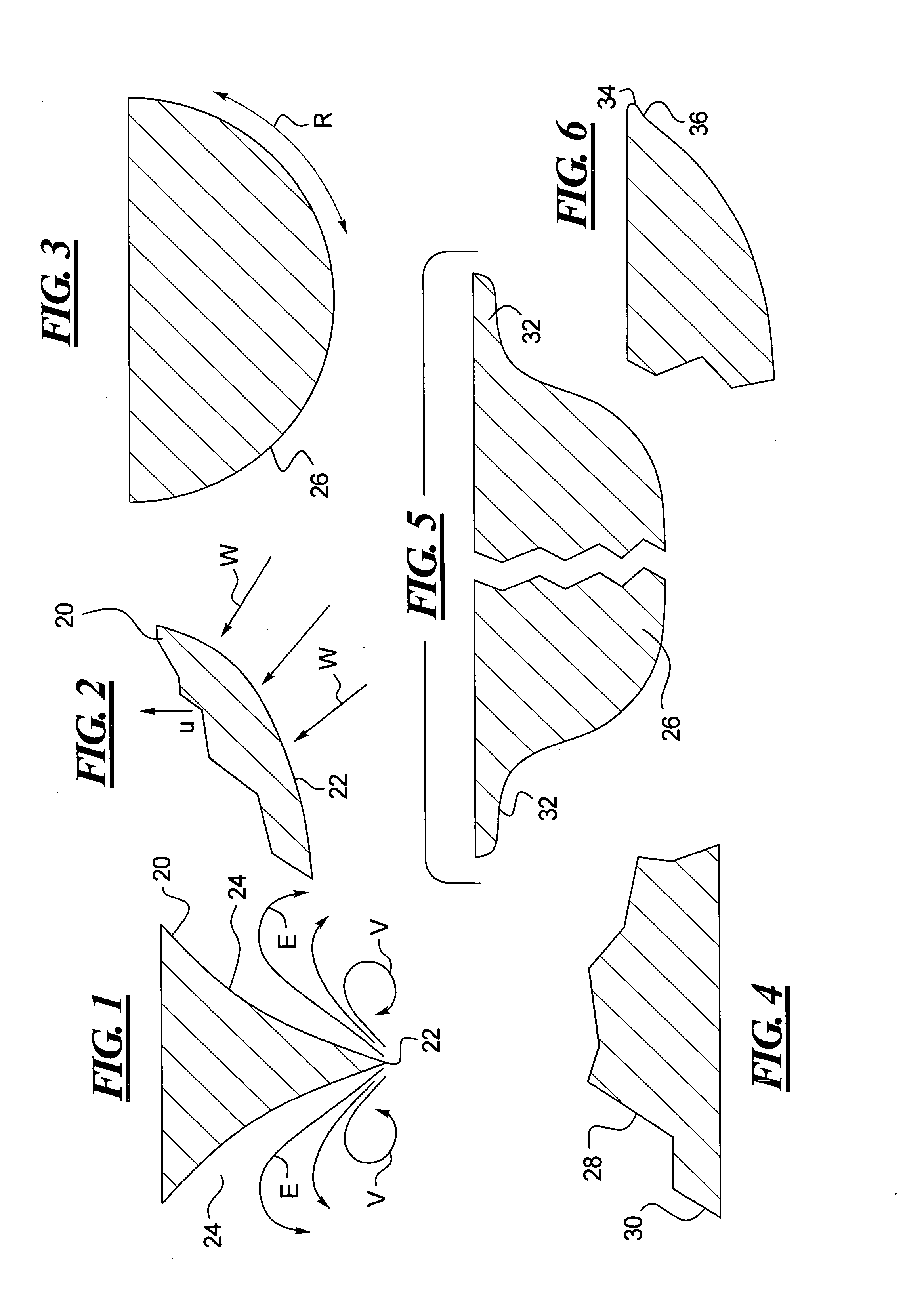
[0055] The sailboat hull of the present invention utilizes hydrodynamic shaping to provide a performance sailboat hull that moves quickly and efficiently through the water. A preferred embodiment of a more optimized hull is demonstrated in an 18 foot sailboat. A front portion of the hull has a shape to ease water entry and to shape the water flow at the front of the boat. FIG. 1 shows a schematic representation of the water entry portion of the present hull in transverse cross section (also see FIG. 14 that shows the present embodiment prototype sailboat from the bow view). FIG. 2 shows this same water entry portion of the hull in the longitudinal starboard side view. In particular, the water entry includes a relatively sharp edge 22 that slices into the water.

[0056] The sharp edge 22 is followed by a pair of outwardly angled concave surfaces 24. These outwardly angled concave surfaces 24 receive and direct the water that is sliced by the edge of the bow and direct it not only up a...


PUM


Abstract

A hull for a boat, for example a sailboat, has a sharply angled front or bow with a curved center crest line providing a entry into the water during forward motion. Sides of the bow are concave. The main body of the hull is shaped as a semicircle in transverse cross section. The upper edge of the hull has a flare that extends laterally outward to form wings along both sides of the hull. The wings begin adjacent the front or bow and gradually increase in the extent of their lateral extension at a mid-position the hull and adjacent the stern. The stern has an angled end extending rearward at the bottom of the hull. A step is provided at the stern. The deck extends from the upper edge of the hull to the edges of the cockpit. The cockpit has curved inside surfaces and a center beam extending along the center of the boat, the center beam having sloping surfaces. An open transom permits water to flow from the cockpit.

Description

BACKGROUND OF THE INVENTION [0001] 1. Field of the Invention [0002] The present invention relates to a winged water surface craft hull, and in particular to a winged hull for a sailboat or powerboat or other watercraft utilizing a winged hull shape. [0003] 2. Description of the Related Art [0004] People have been moving about on the surface of lakes and seas with success for perhaps 10,000 years or more. Ocean dwelling creatures, on the other hand, are the genetic result of a few million years of nature's evolutionary natural selection survival process and so have a significant ‘research and development’ head start when it comes to moving about in water. Thus, it is likely that large fast fish or water-based mammals are almost perfectly optimized for moving large bodies efficiently in the water. A better understanding of how whales, sharks, dolphins and other large-bodied ocean creatures move so effortlessly and rapidly in an incompressible fluid, and apparently with such low energy...

Claims


Application Information

Patent Timeline
IPC IPC(8): B63H9/00B63B1/00B63B1/32
CPCB63B1/04Y02T70/12B63B1/32Y02T70/10
Inventor ASHDOWN, GLYNN RUSSELL
Owner ASHDOWN GLYNN RUSSELL
Why Eureka
Try Eureka