Brazed structure and method of manufacturing the same

Inactive Publication Date: 2006-11-16
DENSO CORP
View PDF6 Cites 15 Cited by
  • Summary
  • Abstract
  • Description
  • Claims
  • Application Information

AI Technical Summary

Benefits of technology

[0007] The present invention is made in view of the foregoing matter, and it is an object of the present invention to provide a brazed structure with an improved brazing quality and a method of manufacturing the same without precisely setting an initial clearance between brazing portions.
[0009] During brazing, the second member more expands than that the first member expands. Thus, the second portion relatively becomes close to the first portion of the first member during the brazing. Namely, the initial clearance defined between the first portion and the second portion is reduced by the difference of coefficient of thermal expansion between the first member and second members. Accordingly, the quality of brazing improves without requiring to precisely set the initial clearance between the brazing portions.

Problems solved by technology

However, there is a limitation to improve the dimensional accuracy while processing the parts.
However, if the tube is made of a material having a high coefficient of elasticity (e.g., copper), it does not easily deform and may cause a spring back.
Accordingly, it is difficult to reduce the clearance.

Method used


Image

  • Brazed structure and method of manufacturing the same
  • Brazed structure and method of manufacturing the same
  • Brazed structure and method of manufacturing the same

Examples


Embodiment Construction

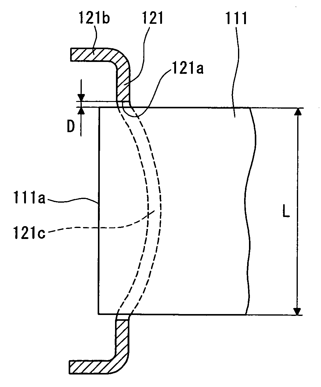
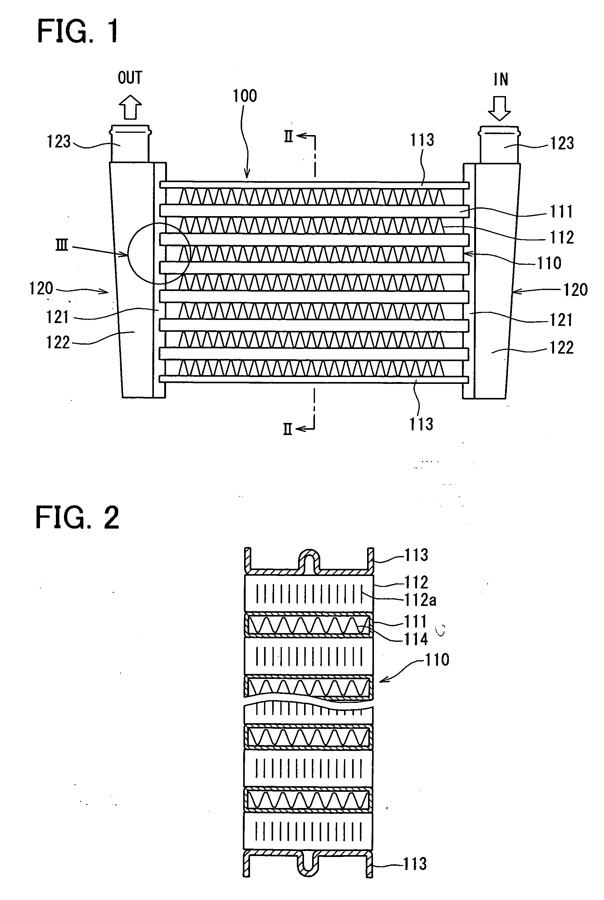
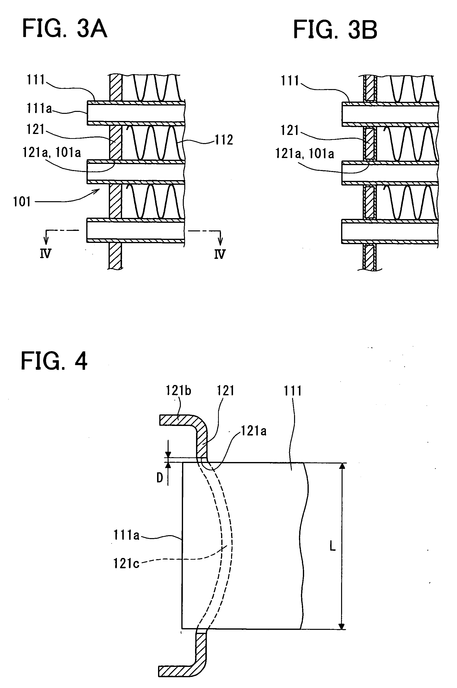
[0019] A first example embodiment of the present invention will now be described with reference to FIGS. 1 to 4. In the first example embodiment, a brazed structure of the present invention is for example employed to a base portion (connecting portion) 101 of an air cooling type intercooler 100.

[0020] The intercooler 100 is a heat exchanger for performing heat exchange between an intake air to be sucked in an engine of a vehicle for combustion and an external cooling air for cooling the intake air. The intercooler 100 has a core portion 110 and a pair of header tanks 120. The intercooler 100 is a large heat exchanger and is for example mounted on a large vehicle such as trucks. Respective parts of the intercooler 100, which will be described later, are made of materials such as copper, copper alloy, or iron to have sufficient thermal conduction and durability.

[0021] Further, connecting portions between respective parts are connected by brazing or welding. For example, a copper bra...


PUM

PropertyMeasurementUnit
Coefficient of linear thermal expansionaaaaaaaaaa

Abstract

In a brazed structure, a first member has a first portion defined by one of a recessed portion and a hole, and a second member has a second portion brazed to the first portion with a copper brazing material. The first member has a coefficient of thermal expansion that is smaller than that of the second member.

Description

CROSS REFERENCE TO RELATED APPLICATION [0001] This application is based on Japanese Patent Applications No. 2005-139112 filed on May 11, 2005 and No. 2005-337626 filed on Nov. 22, 2005, the disclosures of which are incorporated herein by reference. FIELD OF THE INVENTION [0002] The present invention relates to a brazed structure and a method of manufacturing the same, which is for example employed to connecting portions between a header tank and tubes of a heat exchanger. BACKGROUND OF THE INVENTION [0003] A heat exchanger in which longitudinal ends of tubes are connected to header tanks is for example known in Japanese Unexamined Patent Publication No. 2002-286395 (U.S. Pat. No. 6,736,197). In such a heat exchanger, the header tank is generally constructed of a tank body and a header plate formed with tube holes. The longitudinal ends of the tubes are inserted in the tube holes and brazed to the header plate. The tubes and the header tanks are for example made of aluminum. [0004] I...

Claims


Application Information

Patent Timeline
IPC IPC(8): F28F9/02
CPCB23K1/0012B23K2201/14B23K2203/12F28D1/0316F28F9/18Y10T29/49373F28F21/085F28F21/089F28F9/0224F28F9/0263F28F9/182B23K2101/14B23K2103/12
Inventor WATANABE, HARUHIKOSUSA, SUMIOHARADA, MASAKI
Owner DENSO CORP
Why Eureka
Try Eureka