Electric motor driven showerhead

a technology of electric motors and shower heads, which is applied in the direction of spray nozzles, spraying apparatuses, physical therapy, etc., can solve the problems of reducing the initial desired effect of pulsating water, reducing the time between pulses, and affecting the effect of massaging, etc., to achieve long battery life, improve massaging effect, and reduce power consumption

Inactive Publication Date: 2006-11-16
YEISER JOHN O
View PDF33 Cites 38 Cited by
  • Summary
  • Abstract
  • Description
  • Claims
  • Application Information

AI Technical Summary

Benefits of technology

[0004] The aforementioned problems are solved and improvements to the massaging effect are provided by the use of miniature battery-powered electric motors or solenoids to actuate valving, rotate nozzles, or actuate nozzles in various axes or planes of motion. Because such electric solenoids and motors are very small and operate with low power consumption, the inventive showerhead can be compact while possessing long battery life. Optionally, the device can be hardwired if desired, using a very low voltage, DC current from a converter plugged into an electrical outlet located at a safe distance from the shower stall. Among the advantages of the inventive showerhead design are that the water pressure is irrelevant to the actuation or energy required to provide the massaging action. This addresses a problem in some areas that have low water pressure, which in the past had been prevented from using massaging showerheads. In addition, the pulsing of the water can be virtually infinitely adjusted to produce the precise massaging effect desired by the user. Where a rotational mechanism is used, the rotational speed of the nozzle or showerhead can be adjusted to the desired speed regardless of water pressure or flow. In an alternate embodiment, an energy storage bladder or piston can be disposed between the water source and the valve body so that a slight pressure build-up occurs during the periods when the valve mechanism is closed. When the valve re-opens the initial release of water will have increased pressure for a more desirable massaging effect. This feature is particularly advantageous in areas that have low water pressure.

Problems solved by technology

The problem with these and other similar designs is that the use of water pressure or flow as the means for energy to actuate a valve or rotate a water nozzle causes the effectiveness to be dependent on water pressure.
To increase the strength of the massage, the user would need to increase the pressure of water and or flow, which has the downside that high water pressure comes into contact with the user's skin, which can be uncomfortable.
In addition, the valve mechanism or rotating mechanism spins faster so that the time between pulses decreases, which reduces the initial desired effect of pulsating water.
On the other hand, if the user wants to reduce the speed of the massager, it can only be accomplished by reducing the flow and or pressure to the driving mechanism.
This reduces the rotational speed and increases the time between pulses, however, the water pressure may be reduced below an effective threshold for producing a massaging sensation.
In addition, if the user has low water pressure, the overall desired effect of any water driven mechanism is reduced significantly to the point that it may not work at all.

Method used


Image

  • Electric motor driven showerhead
  • Electric motor driven showerhead
  • Electric motor driven showerhead

Examples


Embodiment Construction

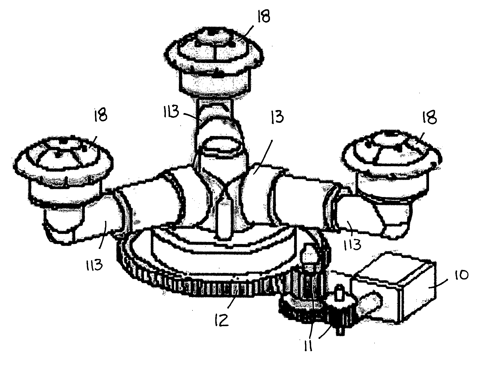
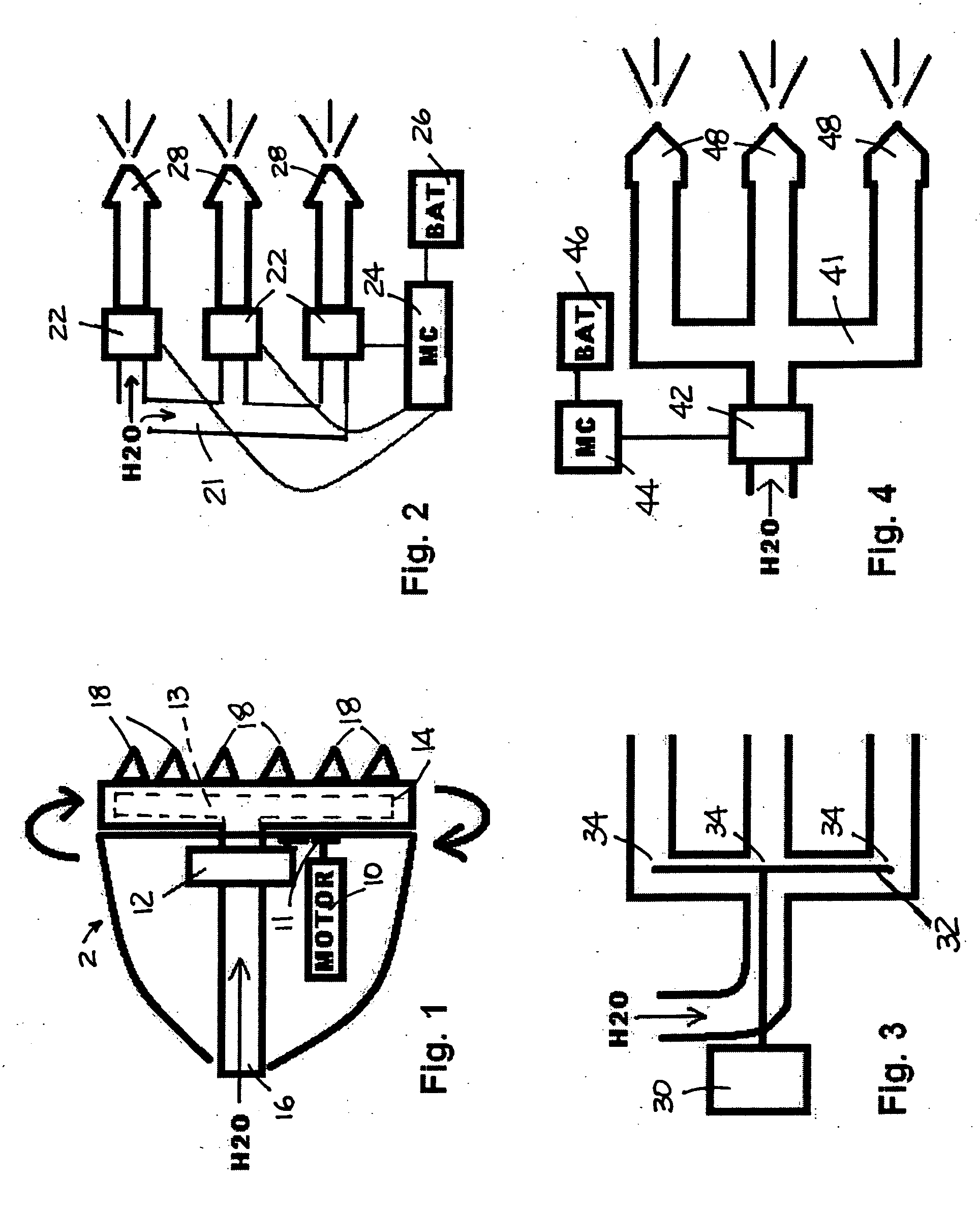
[0017] As illustrated in FIG. 1, a first embodiment of the inventive showerhead 2 utilizes a mini- or micro-electric motor 10 to drive, either directly or through a gear reduction, by gear 12, the face plate 14 of the showerhead causing it to rotate. As illustrated drive gear assembly 11 transfers rotational force from motor 10 to gear 12. Water is introduced through water inlet 16 and into an interior cavity or manifold 13 within face plate 14. A plurality of nozzles 18 is disposed in or on the outer surface of face plate 14 to release streams of water that rotate as manifold 13 and plate 14 rotate, producing a massaging action. In the more detailed illustration in FIG. 9, water entering through inlet 16 is directed into manifold 13 which distributes the water to nozzles 18. The manifold 13 and nozzles 18 rotate with along with face plate 14, as does the axial tube 15. Axial tube 15 is connected to inlet 16 by way of a rotating joint that permits water to flow continuously while ax...


PUM


Abstract

The pulsating spinning showerhead includes a water inlet, water channels for distributing water from the water inlet, and spray nozzles for receiving water from the water channels and projecting a water stream out of the showerhead. At least one valve controls water flow to the spray nozzles. One or more micromotors provides alternating activation of valve so that the spray nozzles receive water in cycles to produce a pulsating output of water. The micromotor and valve are powered by a low voltage power source. In the preferred embodiment, the power source is one or more batteries.

Description

RELATED APPLICATIONS [0001] This application claims the priority of provisional application Ser. No. 60 / 633,903, filed Mar. 21, 2005, which is incorporated herein by reference in its entirety.BACKGROUND OF THE INVENTION [0002] The current technology for massaging showerheads uses internal valves in the showerhead operated via water pressure. One design involves the use of a turbine wheel inside the showerhead which will spin when water is directed into it. The turbine is connected to or has small holes in it that cause it to act like a rotary valve that opens and closes a water passage as it spins around. The resulting water output is a pulsating stream of water, which produces a massaging action. A variation of the turbine involves connecting individual nozzles to a turbine wheel or an eccentric shape which, when water comes in contact with it, either wiggle or spin. This motion is transferred to the water tip, causing them to wiggle, thus providing a water stream that oscillates i...

Claims


Application Information

Patent Timeline
Patent Type & Authority Applications(United States)
IPC IPC(8): B05B3/00
CPCB05B12/06A61H9/00B05B1/083B05B12/04B05B3/02B05B3/14B05B1/18B05B1/185
Inventor YEISER, JOHN O.
Owner YEISER JOHN O
Why Eureka
Try Eureka