
Trussed embankment dam and wall structure

a technology of embankment dams and walls, applied in the direction of buttress dams, artificial islands, excavations, etc., can solve the problems of easy weather, poor landscape, and inability to significantly improve the landscape, and achieve the effect of enhancing the reinforcing effect of the structure and good force transmission

Inactive Publication Date: 2006-11-16
LI PIAO CHIN
View PDF6 Cites 9 Cited by
  • Summary
  • Abstract
  • Description
  • Claims
  • Application Information

AI Technical Summary

Benefits of technology

[0007] Therefore, it is a primary objective of the present invention to provide a trussed embankment dam and wall structure to overcome the shortcomings of the traditional cantilever type or gravity type wall and embankment dam structures that have a single function, a monotonic landscape, a long and complicated construction period, and a difficult maintenance and repair. The invention is designed with a multidirectional structure and developed for multifunctional purposes and applications, not only achieving the effects for safety and maintenance, but also improving the environment, enhancing the landscape, and facilitating the ecological development.
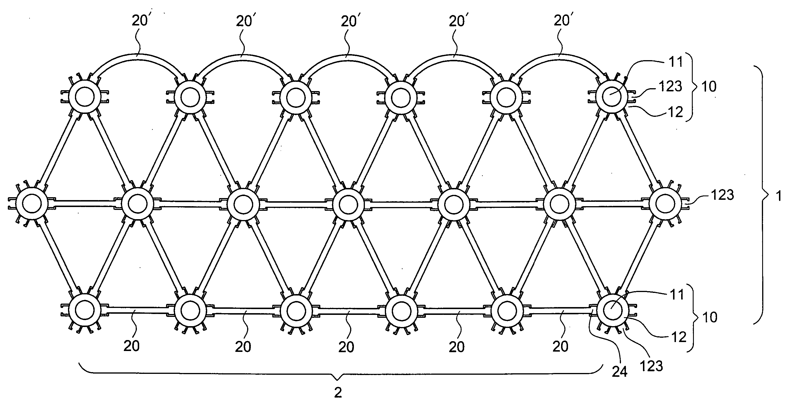
[0009] Firstly, the general truss structure uses a joint as a force exerting point to transmit and disperse the force through the rod member and the force is finally transmitted to the supporting structure of the truss structure and guided into the stratum. In this process, each joint is not related directly to the rod member and the support of the structure, but each joint of the trussed embankment dam and wall structure is disposed directly on the cantilever structure. Meanwhile, each cantilever structure concurrently provides a supporting effect, and the rod member is coupled to each joint, and thus each joint and each rod member of this structure are related. In other words, the centralized supporting type truss structure is converted into a dispersive supporting type truss structure.
[0013] Further, several cantilever structures of the cantilever structure group can be combined to form a subgroup, and such subgroup can be considered as an independent cantilever structure. In other words, the whole structure can be divided into subgroups, and each subgroup can resist forces independently. The rod members can be connected in a subgroup for transmitting and dispersing forces. For example, three cantilever structures are bound into a subgroup, and the rod member in a rod member group can use other rod members to combine two or more rod members, so as to achieve a good force transmitting effect. Further, the whole structure can add an accessory equipment to enhance the reinforcing effect of the structure. For example, the force is introduced to the rear of the rod member of the joint, and a tire net is laid and connected to the rod member, and then the tire net is filled and covered with soil, so that an obstructing effect is produced between the tire and the soil filling to share a portion of forces exerted onto the structure.
[0014] In the trussed embankment dam and wall structure of the present invention, modifications can be made for the foregoing basic architecture. For example, the supporting effect of the lower portion of the anchor supporting pillar of the cantilever structure group installed into the stratum can be substituted by the friction produced at the stratum by the weights of the subgroup and the filling soil, so that the lower portion of the anchor supporting pillar can be cancelled and its supporting effect can be replaced by the friction at the bottom of the structure. In the meantime, the connecting member can be divided and integrated directly with the rod member and then coupled to the multidirectional connecting board to act as a structure for the joint effect. In the whole structure, the upper portion of the anchor supporting pillar can be shortened, and the connection of the rod member and the multidirectional connecting board by the connecting member can be used to replace the shortened portion, or even the anchor supporting pillar can be cancelled by using the weights of the structure and filling soil as well as the connection of the connecting member, rod member and multidirectional connecting board to substitute the actions at the upper and lower portions of the anchor supporting pillar. The weights of the structure and the filling soil and the internal actions of the structure can achieve the same effect of a basic architecture.

Problems solved by technology

Firstly, they come with a single function of safety and maintenance only, and have no other functions.
Secondly, their physical planes and landscapes are monotonic, and the wall structure is basically a level surface, and thus giving a poor landscape.
Even if these structures are made by using stylish moldboards, the landscape still cannot be improved significantly.
Thirdly, these two structures adopt a cast-in-place process to assemble steel bars and moldboards and cast concretes at the spot, and thus the construction schedule may be delayed by climates easily.
Fourthly, these structures produce an isolating effect, and the wall structure blocks the route of species.
Fifthly, these structures cannot be maintained or repaired easily, and if a portion of the wall structure or foundation is damaged, it will be difficult to find a good way to fully fix the damaged portion.
Sixthly, these structures cannot be used for emergency uses, and thus it is impossible to use these structures as emergency protective measures.
As a result, the present structures come with a single application only and a monotonic planar landscape, and the insolating effect blocks the route of species movements and makes the species exchange difficult.
Since these structures can be built with a cast-in-place process and certain materials, the structures of this sort cannot be used for emergency.

Method used


Image

  • Trussed embankment dam and wall structure
  • Trussed embankment dam and wall structure
  • Trussed embankment dam and wall structure

Examples


Embodiment Construction

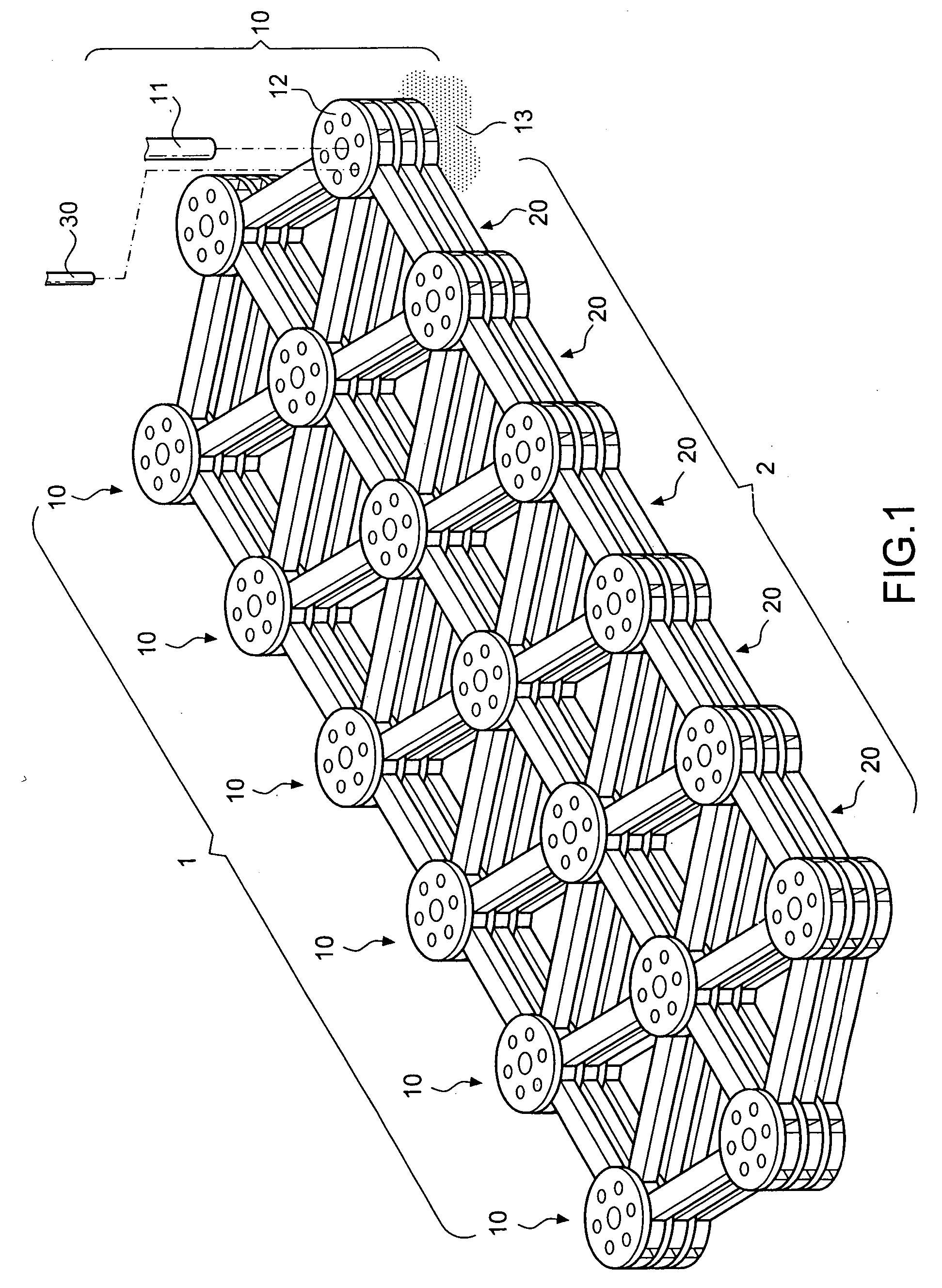
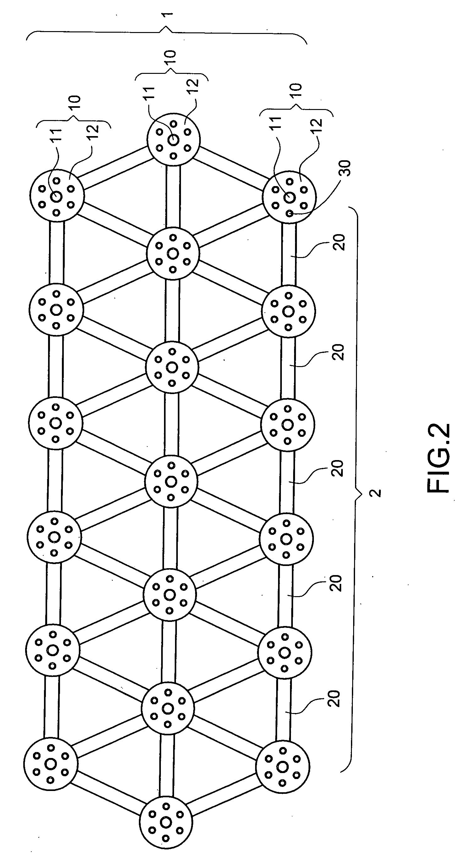
[0030] Referring to FIGS. 1 and 2 for the perspective view and the top view of a trussed embankment dam and wall structure respectively, the structure comprises:

[0031] a cantilever structure group 1, and each cantilever structure 10 including an anchor supporting pillar 11 and a multidirectional connecting board 12, wherein the anchor supporting pillar 11 anchors its lower portion to a supporting stratum or foundation 13 to form a support for the cantilever structure, and the upper portion of the anchor supporting pillar 11 installs at least one multidirectional connecting board 12 to constitute a truss joint structure; and

[0032] a rod member group 2 and both ends of any one of the rod members 20 being integrated with the joint by a connecting member 30 to define a hinge effect, such that the whole structure becomes a trussed embankment dam and wall structure.

[0033] The cantilever structure group 1 and the rod member group 2 of the foregoing structure come with specific quantity ...


PUM


Abstract

A trussed embankment dam and wall structure includes a cantilever structure group and a rod member group, and each cantilever structure of the cantilever structure group includes an anchor supporting pillar and a multidirectional connecting board. The lower portion of the anchor supporting pillar is built at a stratum or foundation to support the cantilever structure, and the upper portion of the anchor supporting pillar installs a multidirectional connecting board to a trussed joint structure. After a force is exerted to a rod member of the invention, the force is acted onto the joints of the cantilever structure and transmitted by other rod members. Therefore, each cantilever structure maximizes the supporting effect and provides a dispersive supporting type structure. Unlike the centralized supporting type truss structure, the invention uses the hollow portion of the structure and the malleability of components to create landscapes, fill soil and plant vegetation.

Description

BACKGROUND OF THE INVENTION [0001] 1. Field of the Invention [0002] The invention relates to a trussed embankment dam and wall structure, and more particularly to an embankment dam and wall structure that uses the concept of a truss to build a dam and wall structure for filling soil, planting vegetation, exchanging species and habitat, and creating beautiful spatial landscape. [0003] 2. Description of the Related Art [0004] Cantilever type or gravity type structures are wall and embankment dam structures commonly used in civil engineering. The gravity type structure uses its own weight to support a toppling torque and a horizontal thrust produced by external forces. The cantilever type structure uses the characteristics of a cantilever to resist the toppling torque caused by external forces as well as the total weight of the structure and the friction produced by the backfill weight at the foundation to resist the horizontal thrust produced by external forces. As to mechanics, both ...

Claims


Application Information

Patent Timeline
IPC IPC(8): E02B7/14
CPCE02D29/0216E02D29/0266E02D29/025
Inventor LI, PIAO-CHIN
Owner LI PIAO CHIN
Learn More