Module component and method for manufacturing the same

Inactive Publication Date: 2006-11-16
PANASONIC CORP
View PDF37 Cites 39 Cited by
  • Summary
  • Abstract
  • Description
  • Claims
  • Application Information

AI Technical Summary

Benefits of technology

[0004] In a module component of the present invention, mounting components and a conductive partition for dividing the mounting components into a plurality of circuit blocks are mounted on a substrate. The circuit blocks partitioned by the partition are covered with a sealing member, and then a conductive film is formed on the surface of the sealing mem

Problems solved by technology

The provision of this cut makes it hard to maintain the bending strength and to reduce warpage of the module component.
As a result, the wiring between the circuit blocks becomes vulnerable to breakage, thereby causing defective circuit operati

Method used


Image

  • Module component and method for manufacturing the same
  • Module component and method for manufacturing the same
  • Module component and method for manufacturing the same

Examples


Example

REFERENCE MARKS IN THE DRAWINGS

[0020]11, 11A, 11B substrate [0021]12 mounting component [0022]13 partition 14 sealing member [0023]15 ground pattern [0024]16 conductive film [0025]201, 601 module component [0026]31, 32 circuit [0027]210, 220 circuit block

DETAILED DESCRIPTION OF PREFERRED EMBODIMENTS

[0028] The module component of the present invention shields a plurality of circuit blocks individually by providing a partition instead of a dividing groove on a substrate. The absence of the dividing groove can secure the bending strength of the module component, reduce defects such as warpage and wiring breakage between circuit blocks, and provide a sufficient shielding effect. The absence can also simplify the manufacturing process of the module component and make the shielding flexible in shape.

[0029] The module component of an embodiment of the present invention will be described as follows with reference to drawings.

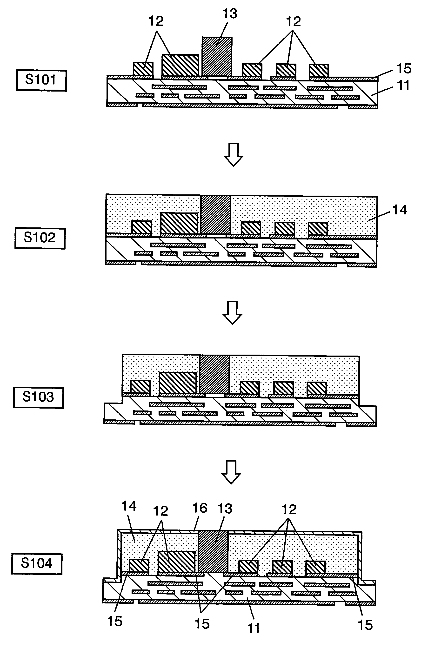
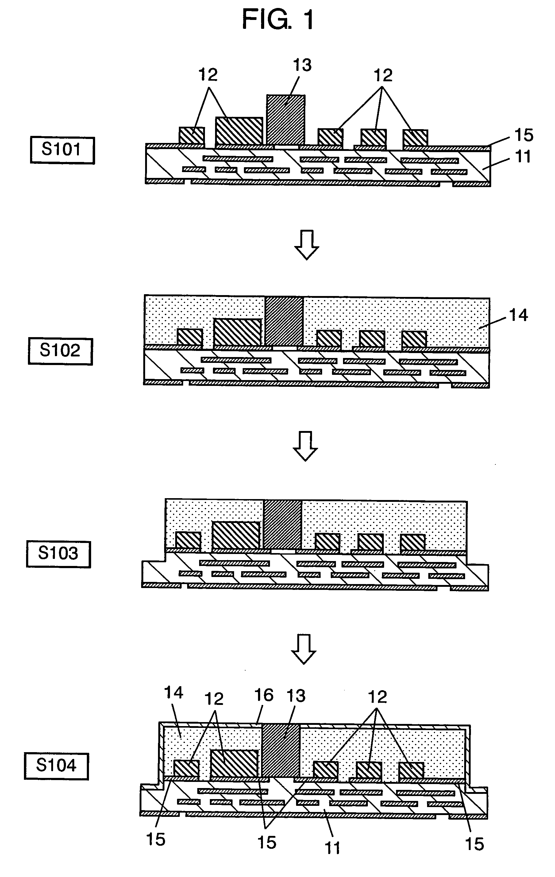
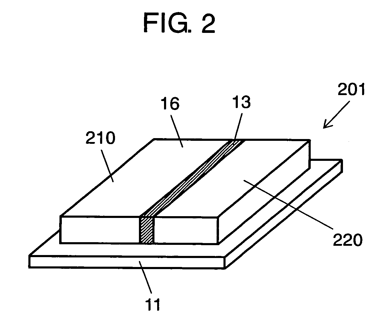
[0030]FIG. 1 show a manufacturing process of the module compo...


PUM


Abstract

A module component in which mounting components and a conductive partition for dividing into a plurality of circuit blocks are mounted on a substrate. The circuit blocks are covered with a sealing member, which is further covered on its surface with a conductive film to electrically shield the circuit blocks individually. This module component can maintain bending strength, with little warpage by a sufficient shielding effect achieved without increasing the number of manufacturing processes.

Description

TECHNICAL FIELD [0001] The present invention relates to a module component provided with an electrical shield, which is used for electronic and communication devices of different types, and also relates to a method for manufacturing the module component. BACKGROUND OF THE INVENTION [0002] A method for manufacturing a conventional module component having an electrical shield is shown in FIG. 14. First, substrate 1 is mounted with mounting components 3 (S141), and then covered with sealing member 4 made of resin (S142). Substrate 1 covered with sealing member 4 is then provided with dividing groove 6 to divide mounting components 3 into desired circuit blocks (S143). Sealing member 4 and dividing groove 6 are coated with metal film-2 on their surfaces by plating or the like (S144) so as to obtain the module component. Metal film 2 has an electrical shielding effect by being connected with ground pattern 5 of substrate 1 and also has the effect of shielding the circuit blocks individua...

Claims


Application Information

Patent Timeline
IPC IPC(8): H01L21/00H01L23/02H01L23/29H01L23/31H01L23/498H01L23/552H05K1/02H05K3/28H05K9/00
CPCH01L23/29H01L23/552H05K1/0218H05K2201/10204H05K9/0022H05K2201/09972H05K3/284H01L2924/15159H01L2924/3025H01L2924/3511
Inventor FUJIWARA, JOJIHIMORI, TSUYOSHITSUNEOKA, MICHIAKI
Owner PANASONIC CORP
Why Eureka
Try Eureka