Method for implanting prosthetic valves

a prosthetic valve and valve leaflet technology, applied in the field of medical devices, can solve the problems of large discomfort and pain for patients, valve leaflets that do not function properly, and substantially unidirectional fluid flow along the length of the vessel, so as to maintain the flow vortex and facilitate the fluid flow

Inactive Publication Date: 2006-11-16
COOK INC
View PDF6 Cites 30 Cited by
  • Summary
  • Abstract
  • Description
  • Claims
  • Application Information

AI Technical Summary

Benefits of technology

[0013] In another embodiment of the present invention, a method for modulating fluid flow through a body vessel is provided. The method includes identifying an existing incompetent valve in the body vessel where the existing valve allows fluid flow therethrough in a first direction and a second direction. The method further includes determining an implantation site for placement of a prosthetic valve at a distance away from the existing valve, providing the prosthetic valve, delivering the prosthetic valve to the implantation site and implanting the valve at the implantation site. Implanting the prosthetic valve at the distance modifies fluid flow through the body vessel by substantially preventing fluid flow in the second direction and substantially maintaining flow vortices formed at the existing valve.

Problems solved by technology

Frequently, fluid flows in a substantially unidirectional manner along the length of the vessel.
In the condition of venous insufficiency, the valve leaflets do not function properly.
Incompetent venous valves can result in symptoms such as swelling and varicose veins, causing great discomfort and pain to the patient.
If left untreated, venous insufficiency can result in excessive retrograde blood flow through incompetent venous valves, which can cause venous stasis ulcers of the skin, pain and discoloration.
Primary venous insufficiency typically occurs where the valve structure remains intact, but the vein is simply too large in relation to the leaflets so that the leaflets cannot come into adequate contact to prevent backflow.
Although sometimes successful, the tight stocking is quite uncomfortable, especially in warm weather, as the stocking must be constantly worn to keep the leaflets in apposition.
The elastic stocking also affects the patient's physical appearance, thereby potentially having an adverse psychological affect.
This physical and / or psychological discomfort can lead to the patient removing the stocking, thereby preventing adequate treatment.
However, these surgeries often result in a long patient recovery time and scarring, and carry the risks, e.g. anesthesia, inherent with surgery.

Method used


Image

  • Method for implanting prosthetic valves
  • Method for implanting prosthetic valves
  • Method for implanting prosthetic valves

Examples


Embodiment Construction

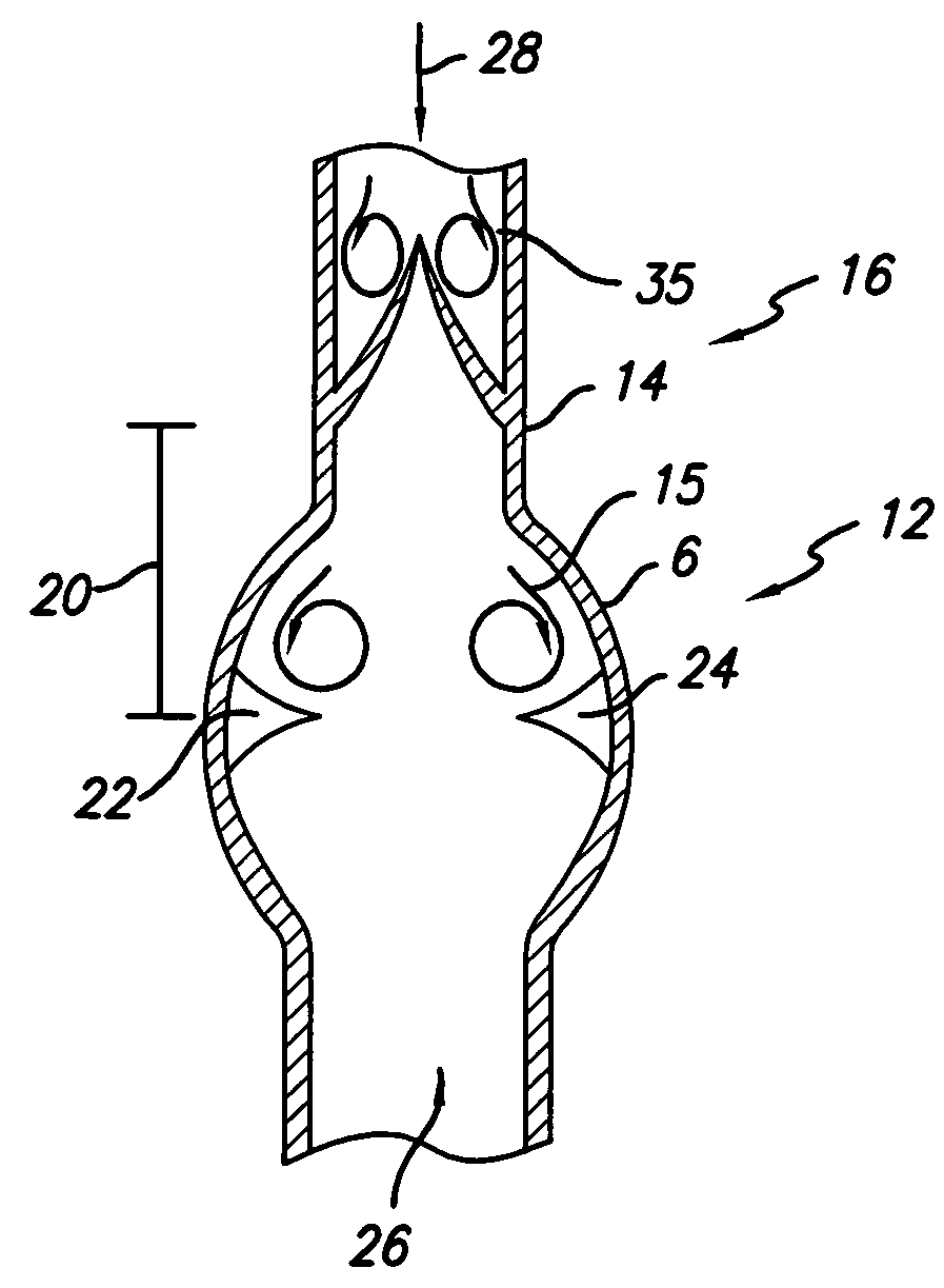
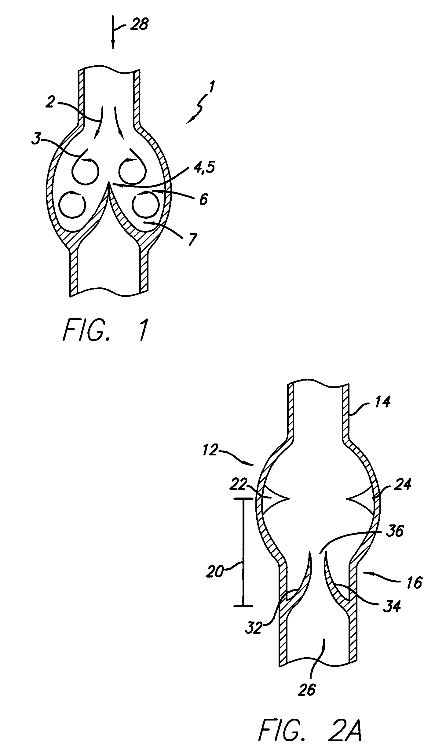
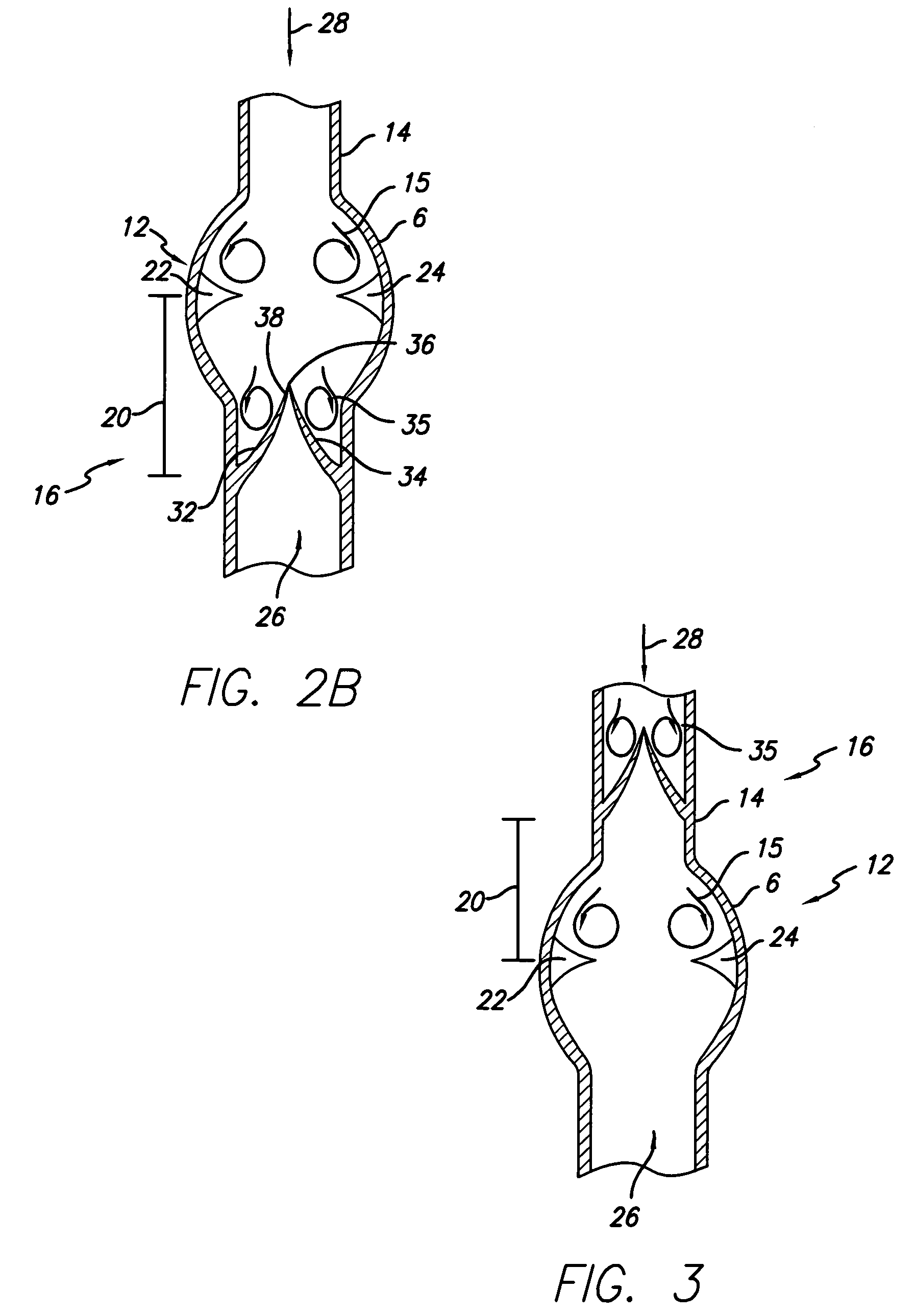
[0025] As described herein, a method is provided for delivering a prosthetic valve to a predetermined position within a body site having fluid flow therethrough and having an incompetent valve. The valves of the present invention are suitable for implantation into vessels. The term vessel as used herein includes ducts, canals, and other passageways in the body, as well as cavities and other locations. For example, the valves of the present invention are suitable for implantation into the vessels of the vasculature, such as veins, for regulating fluid flow through the vessel. The valves of the present invention may also be implanted in a passageway of the heart to regulate the fluid flow into and out of the heart. The incompetent valve may be an existing natural valve or an existing prosthetic valve. The prosthetic valve of the present invention may be placed within a vessel such that any retrograde flow vortices formed at the incompetent valve continue to form to flush out fluids co...


PUM


Abstract

Methods for implanting a prosthetic valve in a body vessel having a fluid flow therethrough are provided. One method includes identifying a position of an existing valve and determining a factor affecting fluid flow in at least one of a first direction and a second direction at the existing valve. The method includes selecting the implantation position for a prosthetic valve at a distance away from the existing valve position in consideration of the factor. The method further includes providing the prosthetic valve for delivery to the implantation position, delivering and implanting the prosthetic valve at the position. The prosthetic valve includes at least one flexible member movable between a first position that permits fluid flow in the first direction and the second position that substantially prevents fluid flow in a second direction.

Description

RELATED APPLICATIONS [0001] This application claims the benefit of U.S. Provisional Application No. 60 / 672,440, filed Apr. 18, 2005, which is incorporated by reference herein in its entirety.TECHNICAL FIELD [0002] The present invention relates to medical devices. More particularly, the invention relates to methods for implantation of an intraluminal device in a body vessel. BACKGROUND OF THE INVENTION [0003] Many vessels in animals transport fluids from one bodily location to another. Frequently, fluid flows in a substantially unidirectional manner along the length of the vessel. For example, veins in the body transport blood to the heart and arteries carry blood away from the heart. [0004] In mammalian veins, natural valves are positioned along the length of the vessel in the form of leaflets disposed annularly along the inside wall of the vein which open to permit blood flow toward the heart and close to restrict back flow. These natural venous valves open to permit the flow of fl...

Claims


Application Information

Patent Timeline
Patent Type & Authority Applications(United States)
IPC IPC(8): A61F2/06
CPCA61F2/2412A61F2/2427A61F2250/0096A61F2250/0002A61F2/2475
Inventor PAVCNIK, DUSANCASE, BRIAN C.PAUL, RAM H. JR.FLAGLE, JACOB A.
Owner COOK INC
Why Eureka
Try Eureka