Bearing for a reciprocating shaft of a reciprocating saw

a reciprocating saw and shaft technology, applied in the field of power tools, can solve the problems of difficult use of traditional reciprocating saws in cramped quarters, inconvenient use of traditional reciprocating saws, and inability to meet the needs of tradesmen, so as to increase the versatility of reciprocating saws, increase the number of tasks, and maintain or improve the effect of efficiency

Inactive Publication Date: 2006-11-23
BLACK & DECKER INC
View PDF10 Cites 30 Cited by
  • Summary
  • Abstract
  • Description
  • Claims
  • Application Information

AI Technical Summary

Benefits of technology

[0010] The present invention seeks to increase the versatility of a reciprocating saw to perform an even greater number of tasks by permitting adjustment of the reciprocating saw's configuration. In one embodiment of the adjustable reciprocating saw disclosed herein, the saw blade is continuously adjustable about two transverse rotational axes. This allows the saw blade to be adjusted to a wide range of positions relative to the saw. This adjustability can be highly beneficial when cutting in confined spaces and with obstacles, when closely following cutting lines, and when cutting small radius curves, among other situations often faced by tradesmen. The present invention also seeks to maintain or even improve the compactness, power, and durability of reciprocating saws.
[0015] In another embodiment, a method of fastening first and second housing portions of a power tool where the first and second housing portions rotate relative to one another comprises the steps of assembling the first and second housing portions together so that bearing surfaces formed on each are engaged with one another, and mounting one or more locking pieces onto one of the first or second housing portions without the use of separate removable fasteners so that the locking pieces engage a surface formed on the other of the first or second housing portions thereby permitting relative rotational movement between the first and second housing portions about an axis of rotation and blocking relative axially movement of the first housing portion away from the second housing portion.

Problems solved by technology

Despite the versatility already possessed by reciprocating saws, the reciprocating saw is not well suited for every task a tradesmen faces.
Traditional reciprocating saws are often not useful where only limited maneuvering space is available around the workpiece to be cut.
Because of their length, traditional reciprocating saws are difficult to use in cramped quarters.
As one example, traditional reciprocating saws are difficult to use inside of a cabinet.
Given the limited maneuvering space inside the cabinet and a relatively long saw, the user often cannot maneuver the saw into position so that the blade can move along the cutting path.
The length of most traditional reciprocating saws greatly hampers these cuts because the saw cannot fit perpendicularly between the joists.
The excavation of such a hole is time consuming and costly for the plumber.
These examples show how the length of traditional reciprocating saws can hamper or even prevent its use for some tasks.
The configuration of traditional reciprocating saws can sometimes make their use awkward and uncomfortable.
The configuration of a traditional reciprocating saw does not provide adequate leverage to control fine cutting by the saw blade.
Partially for this reason, it is often difficult to make small radius cuts or to closely follow a fine cutting line with a traditional reciprocating saw.
The lack of adjustability of traditional reciprocating saws can impede their use.
Because the saw has only one direction of cut and no provision to adjust the configuration of the saw blade relative to the body and handle of the saw, the user must sometimes hold the saw in an awkward and uncomfortable position.

Method used


Image

  • Bearing for a reciprocating shaft of a reciprocating saw
  • Bearing for a reciprocating shaft of a reciprocating saw
  • Bearing for a reciprocating shaft of a reciprocating saw

Examples


Embodiment Construction

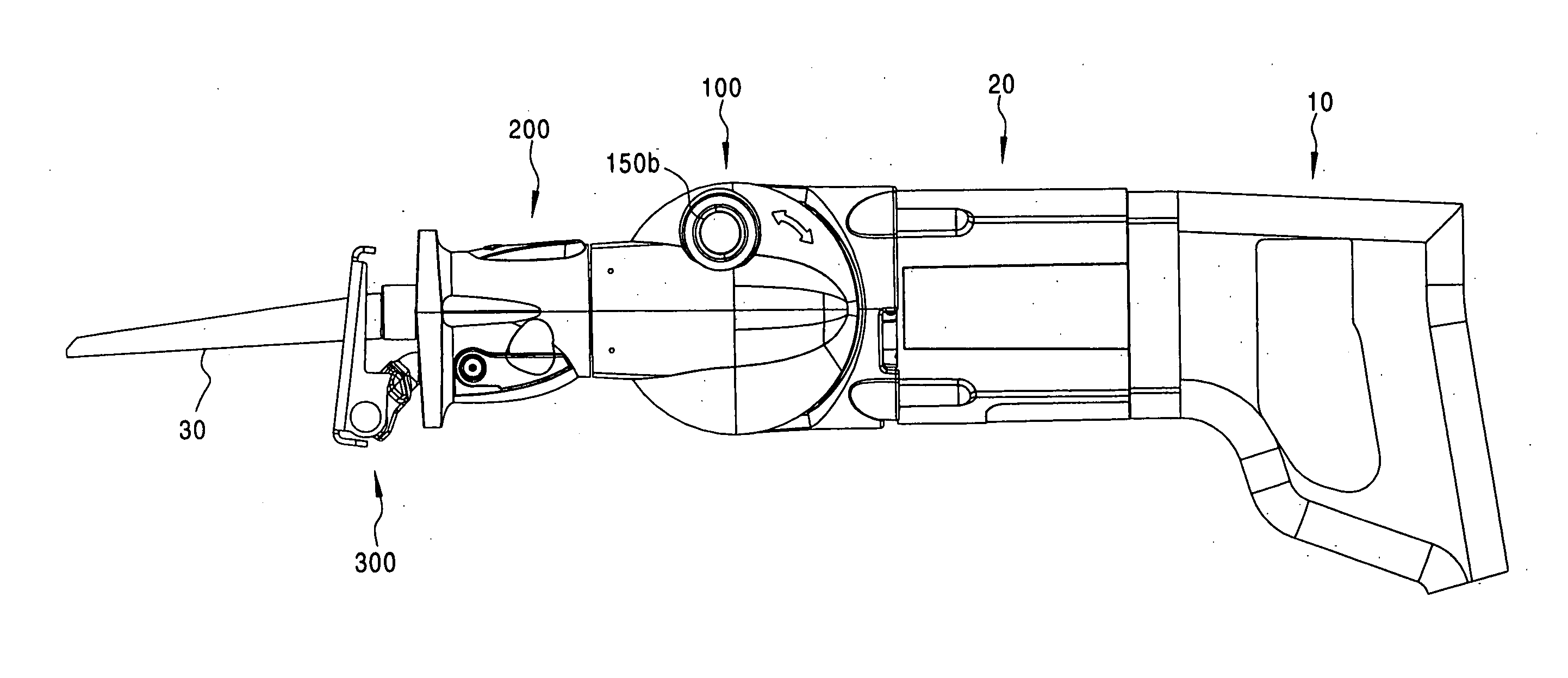
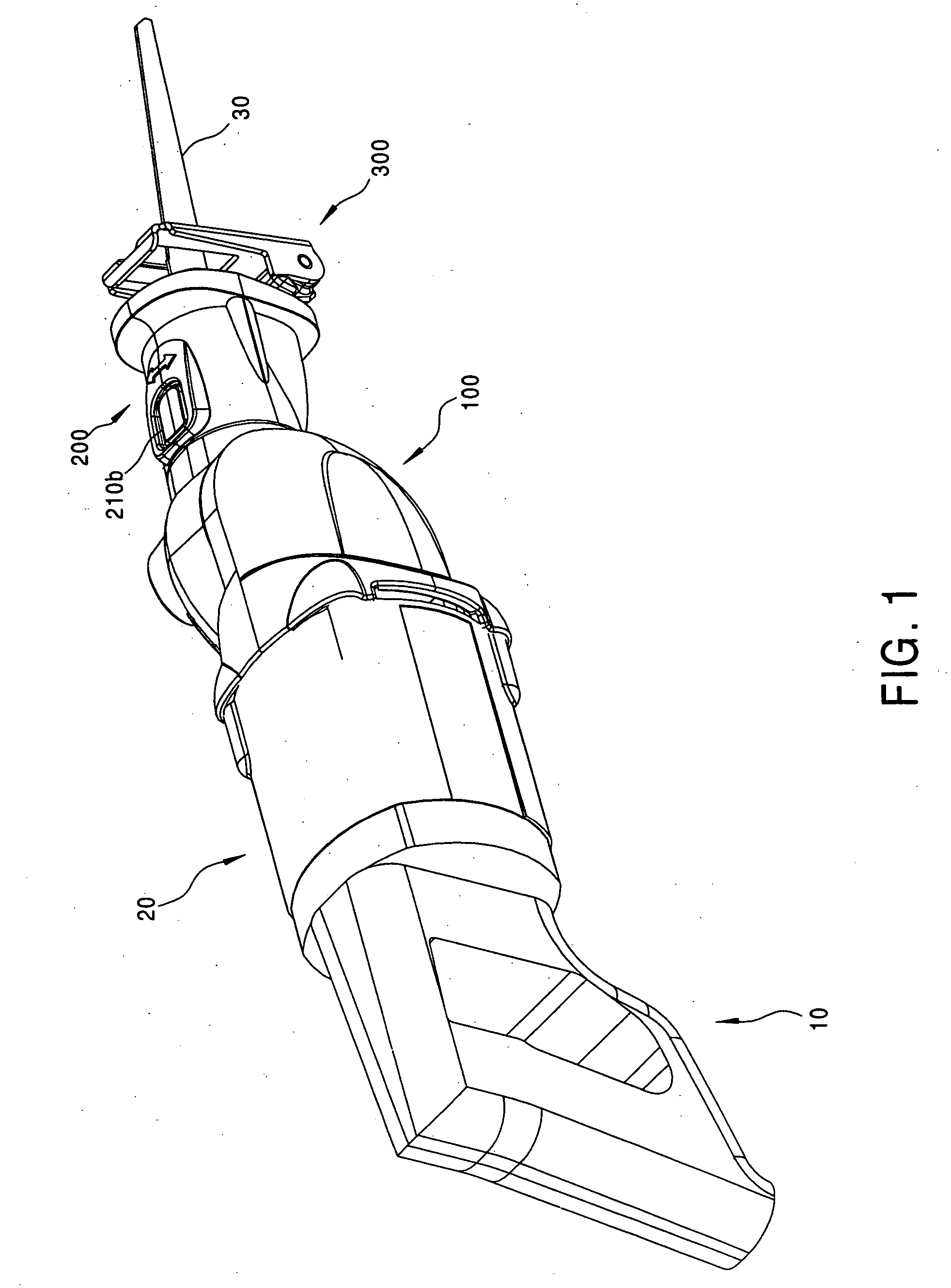
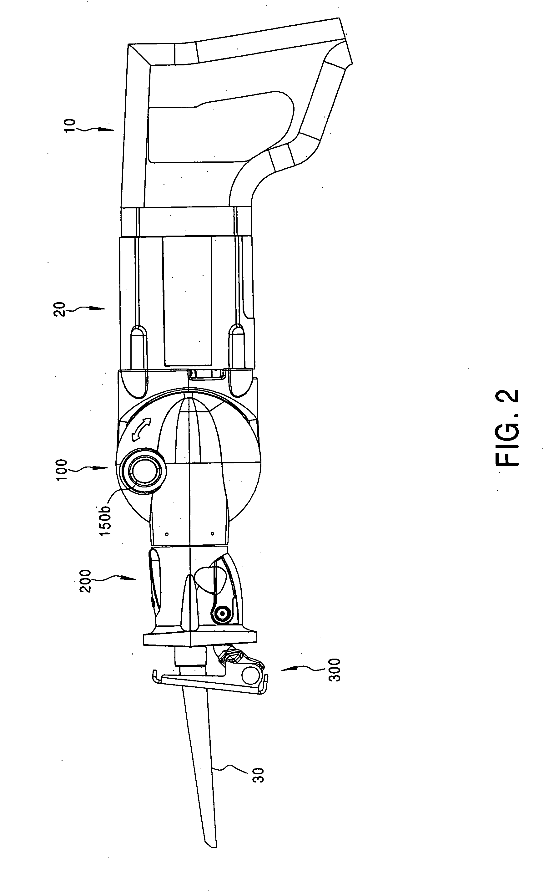
[0046] To illustrate the invention, a preferred embodiment of a reciprocating saw which is a composite of all of the individual features of the invention will be described in detail. However, each of the individual features of the invention may be used separately or in combination with only some of the other features, as will be recognized by those skilled in the art. The scope of protection of the invention is not intended to be limited to a saw embodying all or most of the individual features of the invention, but encompasses any saw which incorporates any of the individual features of the invention as separately recited in the appended claims.

[0047] The term reciprocating saw as used herein shall be construed to mean any saw with a saw blade that has at least a back-and-forth, i.e., reciprocating, motion in a direction generally parallel to the longitudinal axis of the saw blade. Thus, for example, orbital action saws having more than one component of motion are reciprocating sa...


PUM

PropertyMeasurementUnit
pivot angleaaaaaaaaaa
distanceaaaaaaaaaa

Abstract

An adjustable reciprocating saw has the ability to adjust the orientation of the saw blade in relation to the rest of the tool. The saw blade can pivot about two transverse axes, one parallel with and one perpendicular to the reciprocating motion axis of the saw blade. The portions of the saw's housing which rotate relative to one another are attached with a rotating joint comprising a pin and groove design. Rotation locks selectively prevent rotation of the saw blade about each axis. The rotation locks can be released through simply depressing buttons on the saw. A rear internal bearing increases the durability and decreases the size of the saw. A keyless adjustable shoe is mounted to the saw.

Description

[0001] This application is a continuation of U.S. patent application Ser. No. 10 / 622,445, filed Jul. 21, 2003, which application is a divisional application of U.S. patent application Ser. No. 10 / 016,944, filed Dec. 18, 2001 (now U.S. Pat. No. 6,671,969).BACKGROUND OF THE INVENTION [0002] 1. Field of the Invention [0003] The field of this invention is power tools, and more particularly reciprocating saws. [0004] 2. Description of Related Art [0005] Reciprocating saws have long been offered by power tool manufacturers and are especially useful to tradesmen in the building industry. Tradesmen such as carpenters, plumbers, electricians, HVAC mechanics, and central vacuuming system installers use reciprocating saws to make cuts in wood, plastic, and metal materials while accomplishing an infinite variety of tasks. The ample power, durability, and ease of use which are characteristic of reciprocating saws make them a versatile tool well suited to accomplish many different jobs. [0006] De...

Claims


Application Information

Patent Timeline
Patent Type & Authority Applications(United States)
IPC IPC(8): B23D49/00
CPCB23D49/11B25F5/02B23D49/167B23D49/162
Inventor PHILLIPS, ALAN GENESCHNELL, JOHN WALTER
Owner BLACK & DECKER INC
Why Eureka
Try Eureka