Method and system for producing synthesis gas, gasification reactor, and gasification system

Active Publication Date: 2006-11-23
AIR PROD & CHEM INC
View PDF27 Cites 44 Cited by
  • Summary
  • Abstract
  • Description
  • Claims
  • Application Information

AI Technical Summary

Benefits of technology

[0023] a pressure shell for maintaining a

Problems solved by technology

These sticky particles in the raw synthesis gas may cause problems downstream of the gasification reactor where the raw synthesis gas is further processed, since undesirable deposits of the sticky particl

Method used


Image

  • Method and system for producing synthesis gas, gasification reactor, and gasification system
  • Method and system for producing synthesis gas, gasification reactor, and gasification system
  • Method and system for producing synthesis gas, gasification reactor, and gasification system

Examples


Embodiment Construction

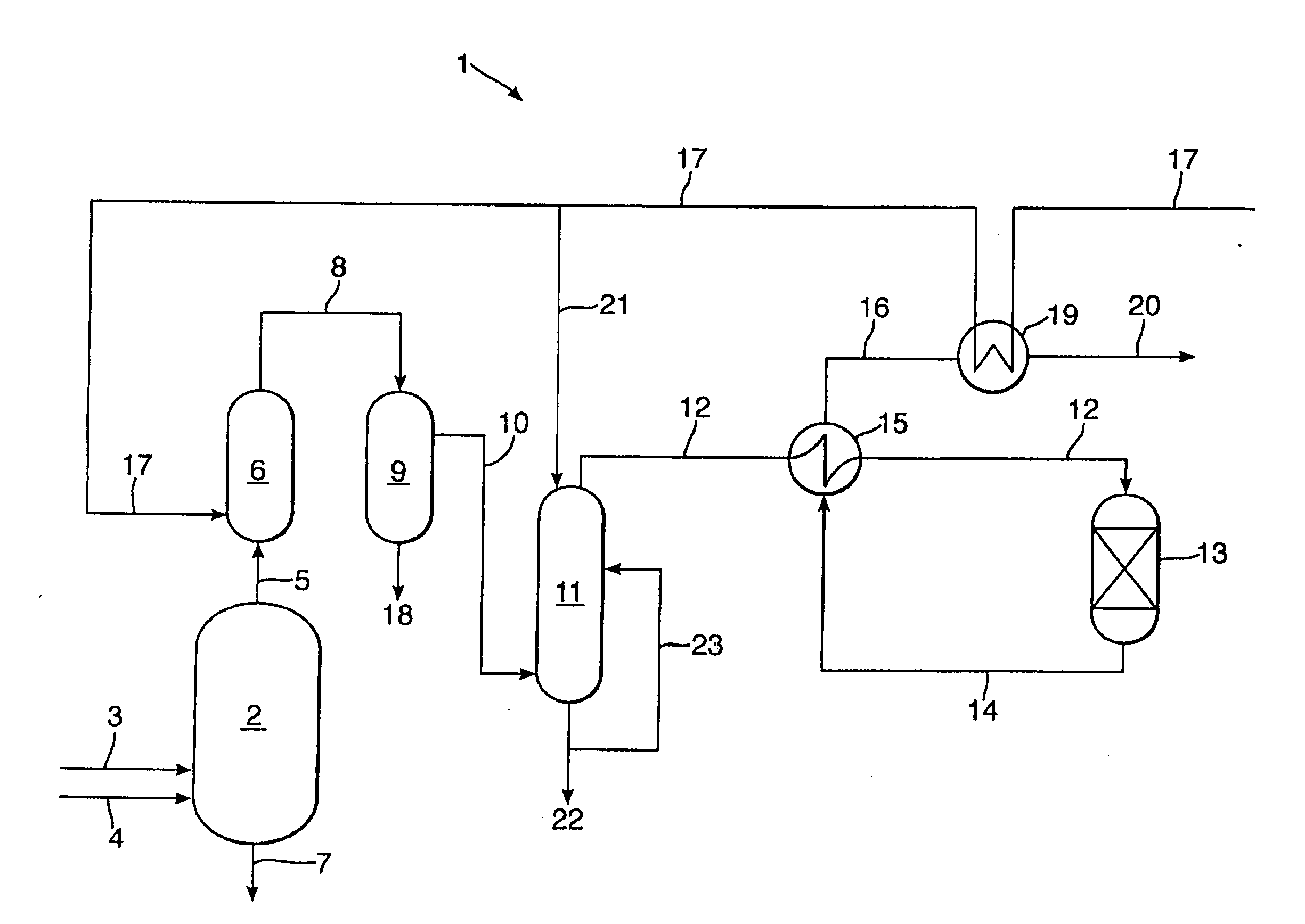
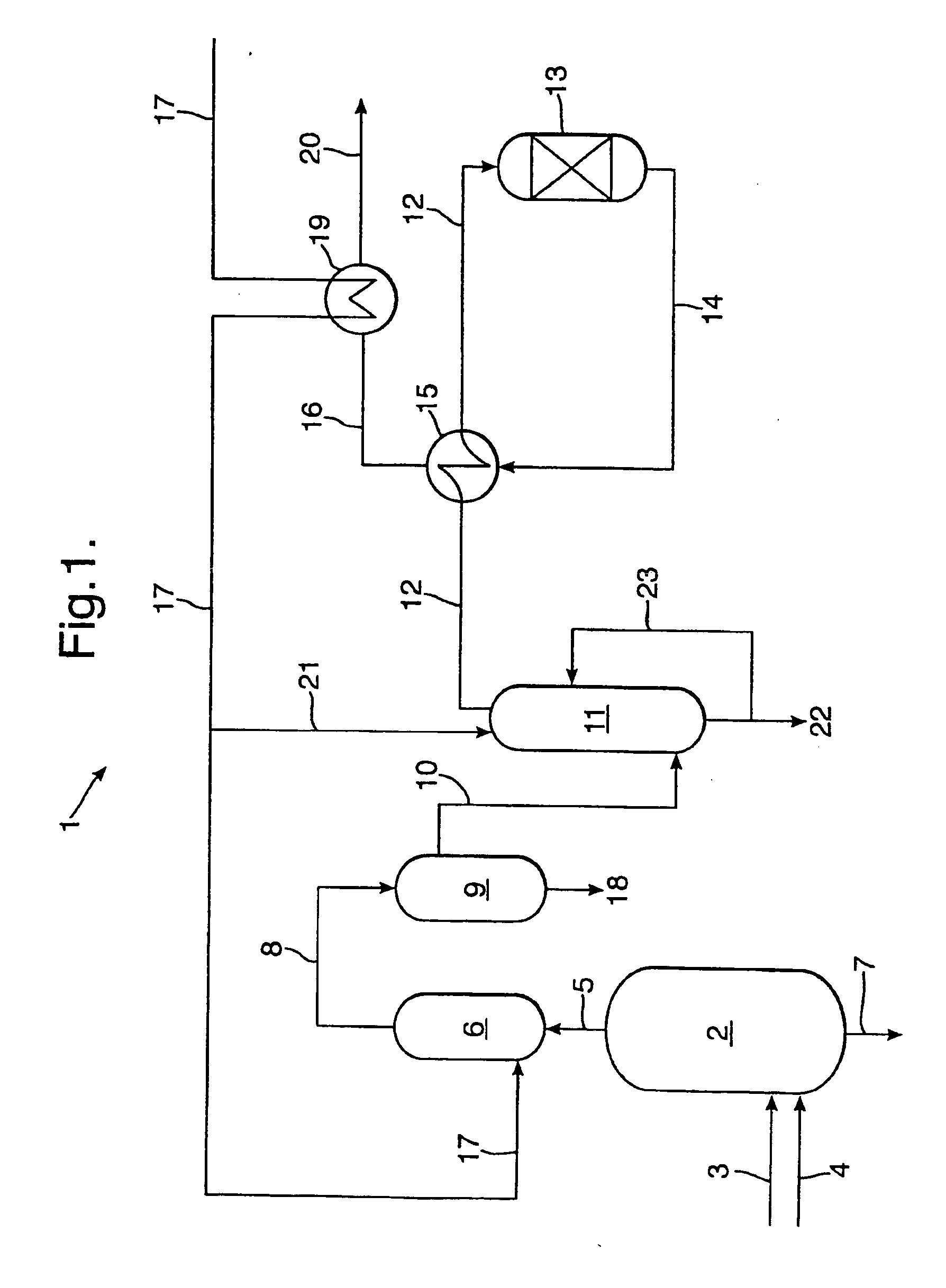
[0041] Reference is made to FIG. 1. FIG. 1 schematically shows a system 1 for producing synthesis gas. In a gasification reactor 2 a carbonaceous stream and an oxygen containing stream may be fed via lines 3, 4, respectively. The term “carbonaceous stream” is used herein as short for any stream containing a carbonaceous material.

[0042] The carbonaceous stream is at least partially oxidised in the gasification reactor 2, thereby obtaining a raw synthesis gas and a slag. To this end, several burners (not shown) are typically present in the gasification reactor 2. Typically, the partial oxidation in the gasification is carried out at a temperature in the range from 1200 to 1800° C. and at a pressure in the range from 1 to 200 bar, preferably between 20 and 100 bar.

[0043] The produced raw synthesis gas is fed via line 5 to a quenching section 6; herein the raw synthesis gas is typically cooled to about 400° C. The slag drops down and is drained through line 7 for optional further proc...


PUM


Abstract

A method and system for producing synthesis gas comprising CO, CO2, and H2 from a carbonaceous stream using an oxygen containing stream. A stream containing a carbonaceous material, and a stream containing oxygen are injected into a gasification reactor, where the carbonaceous stream is partially oxidised to obtain a raw synthesis gas. The raw synthesis gas is removed from the gasification reactor and directed into a quenching section wherein a liquid, preferably water, is injected in the form of a mist.

Description

CROSS REFERENCE TO EARLIER APPLICATIONS [0001] This application claims priority under 35 USC §119 of European patent application number 05103619.2, filed May 2, 2005. FIELD OF THE INVENTION [0002] In one aspect, the present invention relates to a method of producing synthesis gas comprising CO, CO2, and H2 from a carbonaceous stream using an oxygen containing stream. [0003] In another aspect, the invention relates to a gasification reactor for performing said method. [0004] In still another aspect, the invention relates to a gasification system comprising a gasification reactor. [0005] In still another aspect, the invention relates to a system for producing a synthesis gas. BACKGROUND OF THE INVENTION [0006] Methods for producing synthesis gas are well known from practice. [0007] An example of a method for producing synthesis gas is described in EP-A-0 400 740. [0008] Generally, a stream containing a carbonaceous material, such as coal, brown coal, peat, wood, coke, soot, or other g...

Claims


Application Information

Patent Timeline
IPC IPC(8): C10J3/46
CPCC10J3/466C10J3/84C10J2300/093C10J2300/0956C10J3/845C10J2300/1807C10K1/101F28C3/06C10J2300/0959
Inventor VAN DEN BERG, ROBERT ERWINVAN DONGEN, FRANCISCUS GERARDUSVON KOSSAK-GLOWCZEWSKI, THOMAS PAULVAN DER PLOEG, HENRIK JANZUIDEVELD, PIETER LAMMERT
Owner AIR PROD & CHEM INC
Why Eureka
Try Eureka