Apparatus and method to synchronize switching frequencies of multiple power regulators

a technology of power regulator and synchronization method, which is applied in the direction of automatic control, process and machine control, instruments, etc., can solve the problems of undesirable noise, unsatisfactory beat frequency generation, and undesirable side effects of one known method of synchronizing oscillators

Active Publication Date: 2006-11-23
TEXAS INSTR INC
View PDF3 Cites 14 Cited by
  • Summary
  • Abstract
  • Description
  • Claims
  • Application Information

AI Technical Summary

Benefits of technology

[0012] The present invention provides a method and apparatus to enable synchronization of multiple switched power regulators with one another. In particular, a control input is provided to cause a decrease in an oscillation frequency of the switching oscillator upon a synchronization signal being present. The decrease in oscillation frequency shifts a switched regulator ramp signal that may be higher in frequency than a synchronization pulse to a frequency lower than the synchronization pulse so as to permit control of the corresponding switched regulator by the synchronization pulse.

Problems solved by technology

In systems with multiple switching regulators running asynchronously, undesirable beat frequencies are generated that occur at the sum and difference frequencies of the multiple oscillator frequencies.
These beat frequencies represent undesirable noise that is injected in to the electrical system.
One known method of synchronization of oscillators exhibits some undesirable restrictions and side effects.
This is an undesirable restriction that can cause other adverse side effects.

Method used


Image

  • Apparatus and method to synchronize switching frequencies of multiple power regulators
  • Apparatus and method to synchronize switching frequencies of multiple power regulators
  • Apparatus and method to synchronize switching frequencies of multiple power regulators

Examples


Embodiment Construction

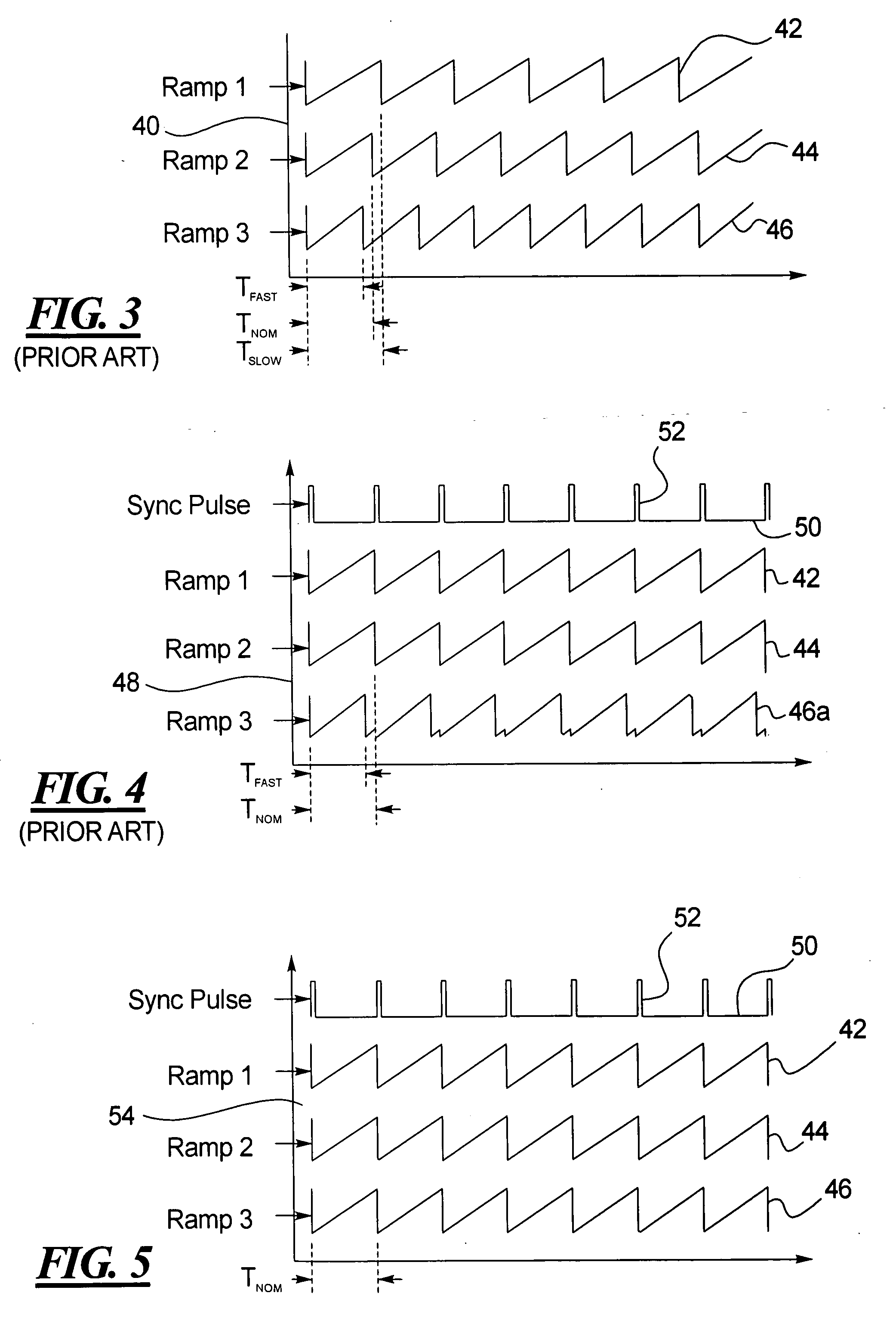
[0023] The present method and apparatus enables the signals of multiple power regulators to be synchronized with one another. Applying the principles of the present invention to the example discussed in the introductory portions of this specification, the ramp signals 42, 44 and 46 of the three regulators are synchronized with one another. In particular, in FIG. 5, the Ramp 1 signal 42, the Ramp 2 signal 44 and the Ramp 3 signal 46 are shown along a common time line in a graph 54 but with the signals shifted to permit comparison. The Sync Pulse signal 50 is also shown.

[0024] As is apparent from a review of waveforms in FIG. 5, after the present invention is utilized, the operation of the same three power regulators is synchronized to a common signal period TNOM. All three regulator signals 42, 44 and 46, including the regulator signal 46 with the highest free running frequency, are now synchronized to the Sync Pulse signal 50. All of the ramp signals exhibit the correct shape for p...


PUM


Abstract

A power supply has a plurality of switching regulators providing a like plurality of regulated output voltages. The oscillators of the switching regulators are synchronized with one another by a synchronization signal. A synchronization signal detector is provided on one or more of the switching regulators to shift the switching frequency of the oscillator to a lower frequency upon detection of a synchronization signal.

Description

BACKGROUND OF THE INVENTION [0001] 1. Field of the Invention [0002] The present invention relates generally to an electrical power supply and in particular to an apparatus and method for synchronizing switching frequencies of multiple power regulators. [0003] 2. Description of the Related Art [0004] Power regulators are used in many electrical devices to provide controlled power to the circuits in the device. The power regulators may be used to translate the voltage to a desired level, to regulate the power to a particular output level, or the like. Power regulators are configured according to several different designs. One such design is a switching power regulator, where an input voltage is switched on and off rapidly and the resulting signal is smoothed to provide an output voltage at a lower level. In many systems, multiple regulators are used to provide multiple output voltages at different levels. [0005] A power regulator 24 is shown generally in FIG. 1, including an input 10,...

Claims


Application Information

Patent Timeline
Patent Type & Authority Applications(United States)
IPC IPC(8): H02M3/156G05B24/02
CPCH02J1/102G05F1/56
Inventor BRASSFIELD, JOEL NATHANRENAUER, JOSEPH GERARD
Owner TEXAS INSTR INC
Why Eureka
Try Eureka