Pixel skew compensation apparatus and method

a technology of skew compensation and apparatus, applied in the field of pixel skew compensation, can solve the problems of signal skew also occurring in multiple twisted pair cables, video sub-pixels arriving out of phase due to cable skew, and achieving the effect of eliminating skew

Inactive Publication Date: 2006-11-23
AVOCENT HUNTSVILLE CORPORATION
View PDF3 Cites 17 Cited by
  • Summary
  • Abstract
  • Description
  • Claims
  • Application Information

AI Technical Summary

Benefits of technology

[0007] The present invention contemplates a different approach to compensating for sub-pixel signal skew. The present invention does not rely solely on physical delay to compensate for skew. However, as will be described in detail below, a small amount of physical delay may be used in conjunction with other aspects of the present invention in order to eliminate skew.

Problems solved by technology

Signal skew also occurs in multiple twisted pair cables that are prevalent today in computer networking.
Generally speaking, skew is the mismatch in arrival times of data on different signal lines where the data was originally transmitted at the same time.
Skew is caused by different propagation rates through different pairs of cable.
When video signals are transmitted on these types of UTP cables, the video sub-pixels arrive out of phase due to cable skew.
For long cables, the skew error can be several pixel times. If these sub-pixels were presented on a video monitor, the display quality would be very poor due to their physical misalignment on the video monitor.
However, the use of physical delay to correct the entire skew has some undesirable characteristics.
Typically, physical delay elements designed to compensate for a large amount of skew are physically large and may limit the bandwidth of the signal being passed through them.
These physical delay elements may also require a complex control mechanism in order to match the delay to the skew associated with a particular cable installation.
As a result of these problems, these physical delay elements are costly.
However, at present computer video rates, this method becomes prohibitively expensive to use for digital displays due to the high speeds inherent in processing these signals.
A significant problem arises, however, when the UTP cable separating the video monitor from the video source is lengthy.
As a result, no adjustment to the phase of a single sampling clock can eliminate or compensate for all of the skew in the analog video signals received by the video monitor.

Method used


Image

  • Pixel skew compensation apparatus and method
  • Pixel skew compensation apparatus and method
  • Pixel skew compensation apparatus and method

Examples


Embodiment Construction

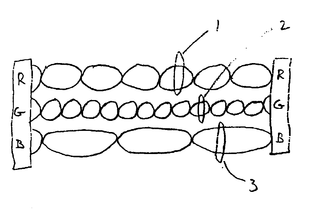
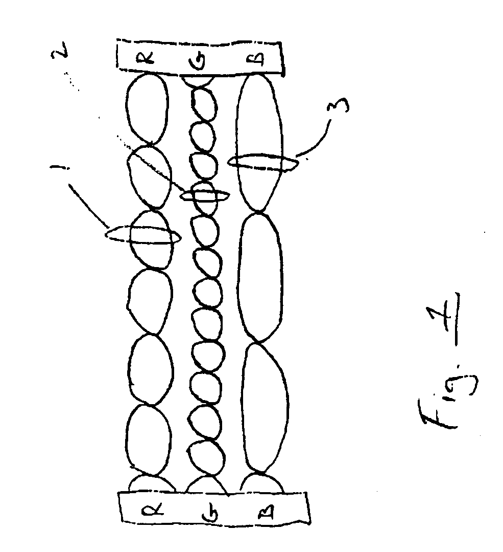
[0026] Referring now to FIG. 1, cables comprised of twisted pair signal wires are typically constructed so that each pair is twisted at a different rate. Different twist rates are used in order to reduce the amount of cross talk coupled between pairs of signal wires. In the representative cable shown in FIG. 1, twisted pairs 1, 2 and 3 are twisted at different rates. It should be noted that the difference in twist rates between pairs is exaggerated in FIG. 1 for purposes of illustration only. Pair 2 has the highest twist rate followed by pair 1 and pair 3, respectively. For the analog video signals being transmitted over the cable of FIG. 1, the analog video signals are comprised of three color components—red, green and blue. In the example shown, the red color component is transmitted over pair 1. While, the green and blue color components are transmitted over pairs 2 and 3, respectively.

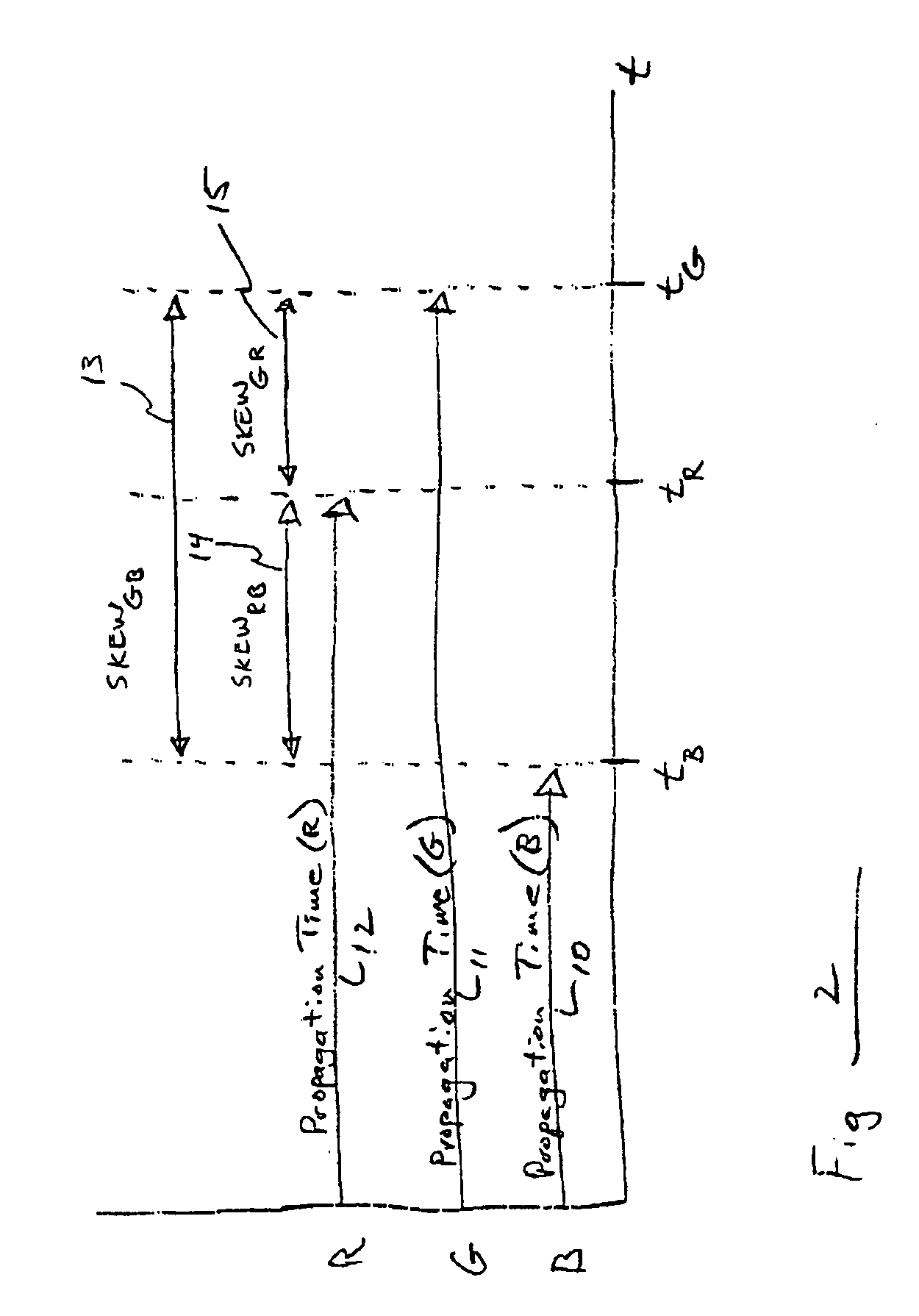
[0027] In general, for a twisted pair of wires, the higher the twist rate, the greater the pro...


PUM


Abstract

A two-stage pixel skew compensation circuit for use with digital display monitors. The first stage of the compensation circuit aligns the edges of the pixels received on the color component signal lines of an analog video signal. The second stage of the de-skew compensation circuit realigns the pixels themselves so that no skew exists between the digitized video color components. The digitized video signals drive a digital video monitor.

Description

CROSS-REFERENCE TO RELATED CO-PENDING APPLICATION [0001] The present application claims priority from co-pending Provisional U.S. Patent application No. 60 / 636,858, filed Dec. 20, 2004, titled “Pixel Skew Compensation Apparatus and Method,” the entire contents of which are incorporated herein by reference.FIELD OF THE DISCLOSURE [0002] This disclosure relates to pixel skew compensation, and to pixel skew compensation circuits, methods and devices for use with digital display monitors. BACKGROUND AND SUMMARY OF THE INVENTION [0003] Signal skew is a well known characteristic in high speed communications and video signal transmission. Signal skew also occurs in multiple twisted pair cables that are prevalent today in computer networking. Generally speaking, skew is the mismatch in arrival times of data on different signal lines where the data was originally transmitted at the same time. Skew is caused by different propagation rates through different pairs of cable. This, in turn, is ty...

Claims


Application Information

Patent Timeline
Patent Type & Authority Applications(United States)
IPC IPC(8): H04N9/68H04N9/64H04N9/74
CPCG09G5/006G09G2320/0209G09G2320/0242G09G5/008H04N5/126H04N5/44H04N9/646H04L25/14
Inventor ODRYNA, VICTORMANSELL, BARRYMANSELL, GAILDESMARAIS, MARKGILGEN, ROBERT L.
Owner AVOCENT HUNTSVILLE CORPORATION
Why Eureka
Try Eureka