X-ray CT image reconstruction method and X-ray CT system

a technology of x-ray ct and image reconstruction, applied in tomography, applications, instruments, etc., can solve the problems of poor image quality, poor spatial and poor image quality, so as to improve the image quality of tomographic image of the delicate lung field and the resolution of tomographic image occurring

Inactive Publication Date: 2006-11-23
GE MEDICAL SYST GLOBAL TECH CO LLC
View PDF24 Cites 11 Cited by
  • Summary
  • Abstract
  • Description
  • Claims
  • Application Information

AI Technical Summary

Benefits of technology

[0041] As mentioned above, according to the present invention, any of the first to fourth enhancements is performed in order to sharpen fan-beam data, parallel-beam data, or tomographic image data. Consequently, striped artifacts derived from conversion from fan-beam data into parallel-beam data according to the MIP method are minimized. A de

Problems solved by technology

However, according to the foregoing background art, the spatial resolution of a tomographic image gets poorer at a point in the image farther away from a point therein associated with a scan center position.
Thus, the image quality is markedly poor.
Consequently, what counts with an X-ray CT image reconstruction method a

Method used


Image

  • X-ray CT image reconstruction method and X-ray CT system
  • X-ray CT image reconstruction method and X-ray CT system
  • X-ray CT image reconstruction method and X-ray CT system

Examples


first embodiment

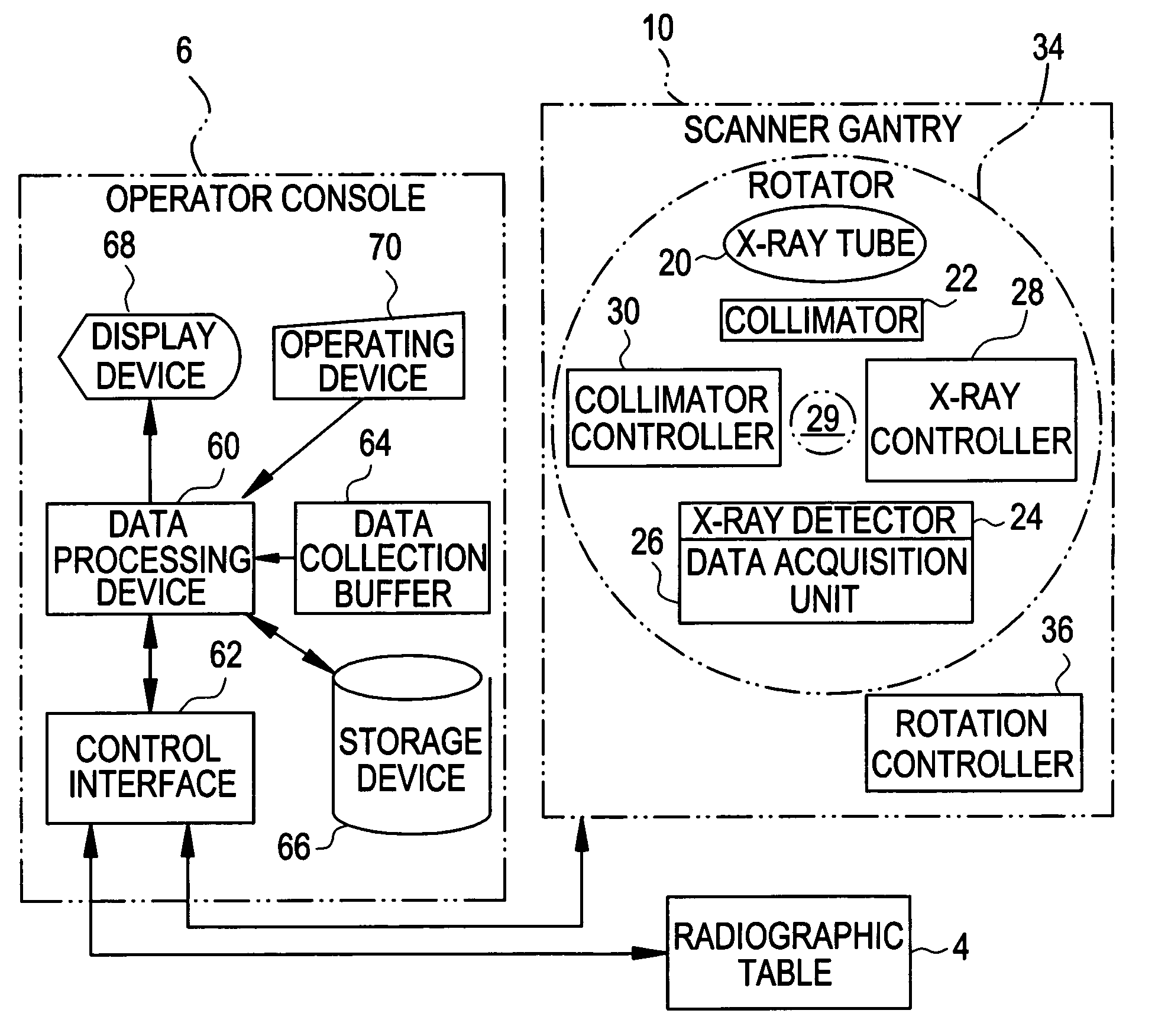
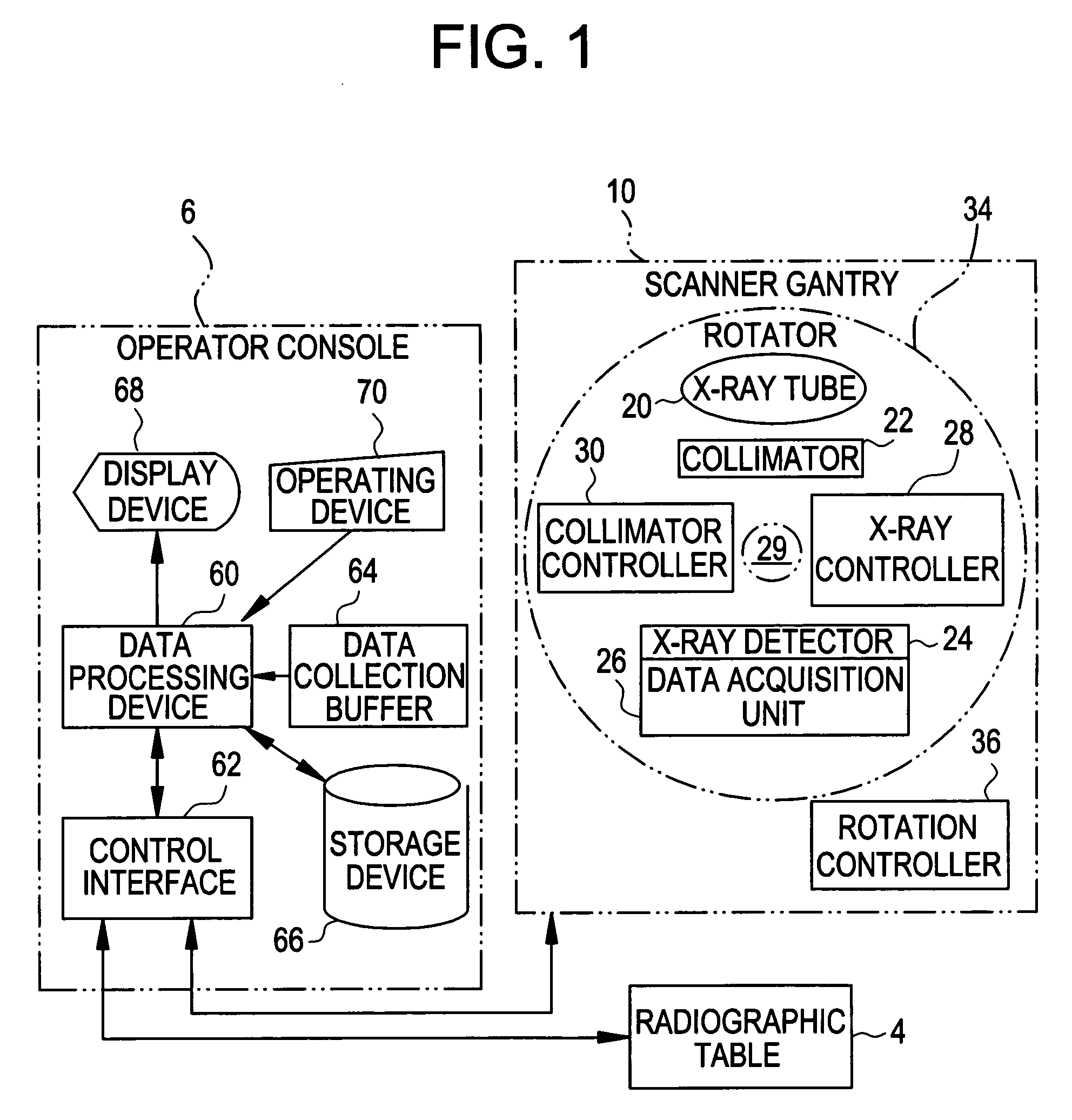
[0057] To begin with, the overall configuration of an X-ray CT system according to the first embodiment will be described below. FIG. 1 is a block diagram showing the X-ray CT system. As shown in FIG. 1, the X-ray CT system includes a scanner gantry 10 and an operator console 6.

[0058] The scanner gantry 10 includes an X-ray tube 20. X-rays that are not shown but are radiated from the X-ray tube 20 are reshaped into a conical X-ray beam, which fans out and is thick, by a collimator 22, and are irradiated into an X-ray detector 24.

[0059] The X-ray detector 24 has a plurality of scintillators set in array in the form of a matrix in a direction in which the fan-beam X-rays spread. The X-ray detector 24 is a multi-channel detector that is wide to have the plurality of scintillators set in array in the form of a matrix.

[0060] The X-ray detector 24 offers an X-ray incidence surface, which is curved in a concave manner, as a whole. The X-ray detector 24 is a combination of scintillators ...

second embodiment

[0091] According to the first embodiment, the first enhancement is performed on views contained in fan-bean data. Alternatively, the second enhancement may be performed on a plurality of fan-beam data items detected at locations in a depth direction. According to the second embodiment, the second enhancement is performed on fan-beam data items identified with different row numbers that are successive in the depth direction.

[0092] A hardware configuration and acquired data items employed in the second embodiment of the present invention are identical to those shown in FIG. 1 to FIG. 3. An iterative description will therefore be omitted. Moreover, a flowchart describing actions to be performed by the data processing device 60 is identical to that of FIG. 4 except that the second enhancement is substituted for the first enhancement at step S403. The iterative description of the actions will be omitted, but only the second enhancement to be performed at step S403 will be described belo...

third embodiment

[0100] According to the first and second embodiments, the first or second enhancement is performed on projection data items contained in fan-beam data and identified with view numbers or row numbers in order to minimize a decrease in a resolution occurring in a reconstructed tomographic image. Alternatively, after image reconstruction is completed, the third enhancement may be performed in order to sharpen pixels so that a pixel in an image whose distance from a pixel associated with a scan center position is longer will be sharpened to a greater degree. Thus, the decrease in a resolution occurring in a perimetric part of an image may be reduced. According to the third embodiment, the third enhancement of sharpening pixels in reconstructed image data so that a pixel whose distance from a pixel associated with a scan center position is longer will be sharpened to a greater degree is performed after completion of image reconstruction.

[0101] A hardware configuration and acquired data ...


PUM


Abstract

An X-ray CT image reconstruction method includes turning a fan-shaped X-ray beam, which is thick and irradiated to a subject, about a subject, detecting projection data items concerning an X-ray beam, which is transmitted by the subject, with the X-ray beam turned by a plurality of successive angles of rotation, enhancing fan-beam data, which includes projection data items detected with the X-ray beam turned by the angles of rotation, so as to sharpen projection data contained in the fan-beam data and acquired along each projection line, producing parallel-beam data, which values thereof defined along parallel projection lines, in relation to each angle of projection using the enhanced fan-beam data, and reconstructing an image using the parallel-beam data.

Description

CROSS REFERENCE TO RELATED APPLICATIONS [0001] This application claims the benefit of Japanese Application No. 2005-148346 filed May 20, 2005. BACKGROUND OF THE INVENTION [0002] The present invention relates to an X-ray CT image reconstruction method and an X-ray CT system in which fan-beam data concerning an X-ray beam that fans out is converted into parallel-beam data concerning parallel X-rays, which are supposed to be projected at an equal angle of projection, in order to reconstruct an image. [0003] Recently, X-ray CT systems use three-dimensional tomographic image data of a subject to produce information on a projection image formed by projecting the three-dimensional tomographic image data in one direction. Methods for producing the information on a projection image include a maximum intensity projection (MIP) method of visualizing maximum pixel values detected in a direction of projection (refer to, for example, Non-patent Document 1). [0004] When the MIP method is adopted, ...

Claims


Application Information

Patent Timeline
IPC IPC(8): H05G1/60A61B6/00G01N23/00G21K1/12
CPCG01N23/046G01N2223/42G01N2223/612G01N2223/419A61B6/583A61B6/03
Inventor KAWACHI, NAOYUKIHORIUCHI, TETSUYA
Owner GE MEDICAL SYST GLOBAL TECH CO LLC
Why Eureka
Try Eureka