Multi-power multi-stage electric heater

Inactive Publication Date: 2006-11-23
SUNBEAN PROD INC
View PDF35 Cites 86 Cited by
  • Summary
  • Abstract
  • Description
  • Claims
  • Application Information

AI Technical Summary

Benefits of technology

[0007] It is an object of the present invention to provide an electric heat

Problems solved by technology

Portable electric heaters are currently limited to a continuous power rating of no greater than 1500 watts.
However, in an enclosed space to be heated, the operation of a heater at 1500 watts or less results in extended heating times. Therefore, th

Method used


Image

  • Multi-power multi-stage electric heater
  • Multi-power multi-stage electric heater
  • Multi-power multi-stage electric heater

Examples


first embodiment

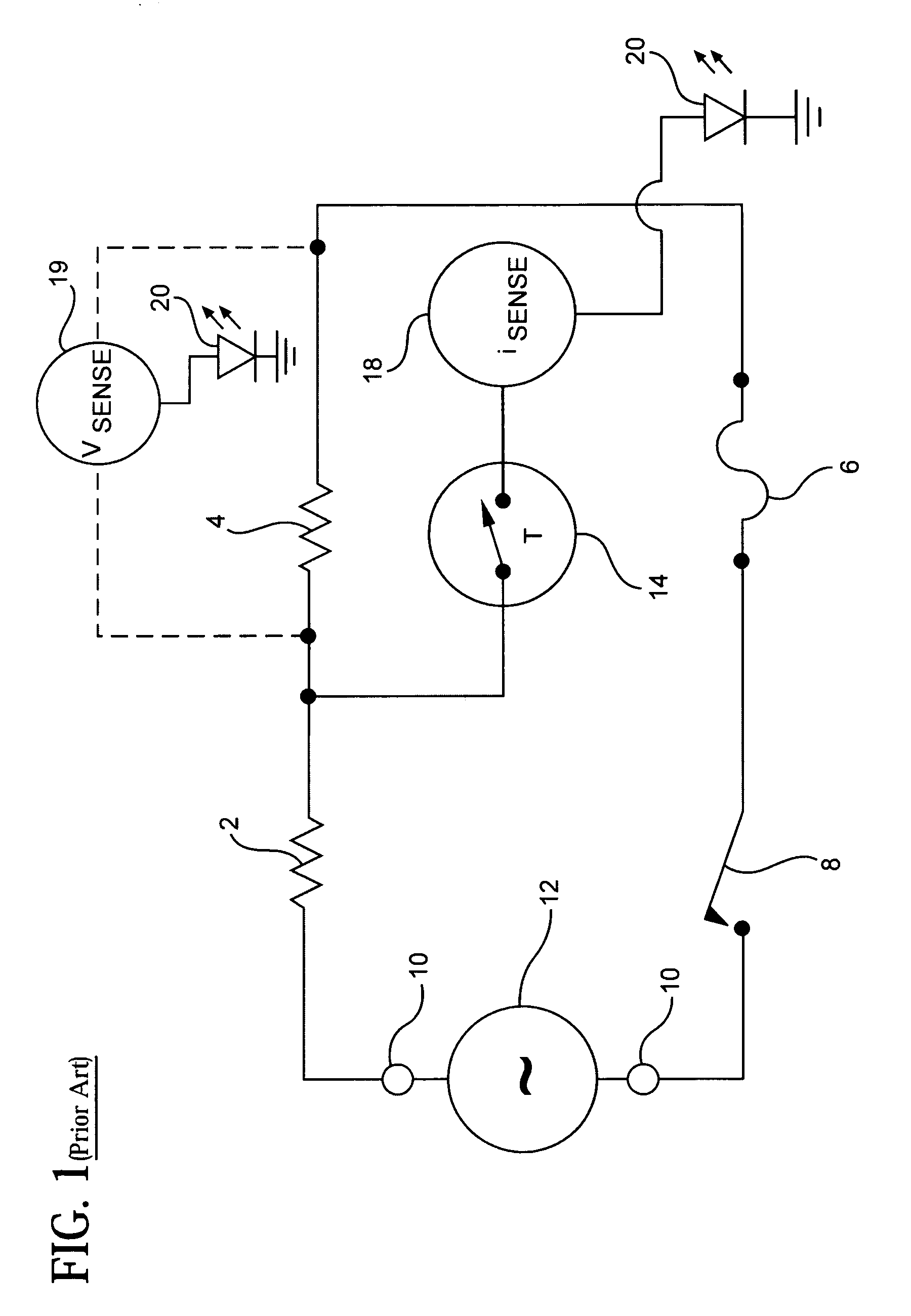
[0033]FIG. 1 is a schematic diagram of a heater circuit described in U.S. Pat. No. 6,233,397, which is incorporated herein by reference. The heater of FIG. 1 includes a series circuit formed by the connection of a first resistive heating element 2, a second resistive heating element 4, a thermal fuse 6 and a high-limit normally closed thermostat 8. Terminals 10 are included to attach the series circuit to an external power source 12.

[0034] The heater circuit of FIG. 1 further includes a thermal switch 14, which is connected in parallel with the second resistive heating element 4. Thermal switch 14 operates in a normally closed (low-resistance) state when the device is at a first temperature, and an open (high-resistance) state upon reaching a second, higher temperature. Preferably, thermal switch 14 is a positive temperature coefficient (PTC) device that latches in the open state until power is removed from the circuit or the user intervenes.

[0035] When the power source 12 is first...

second embodiment

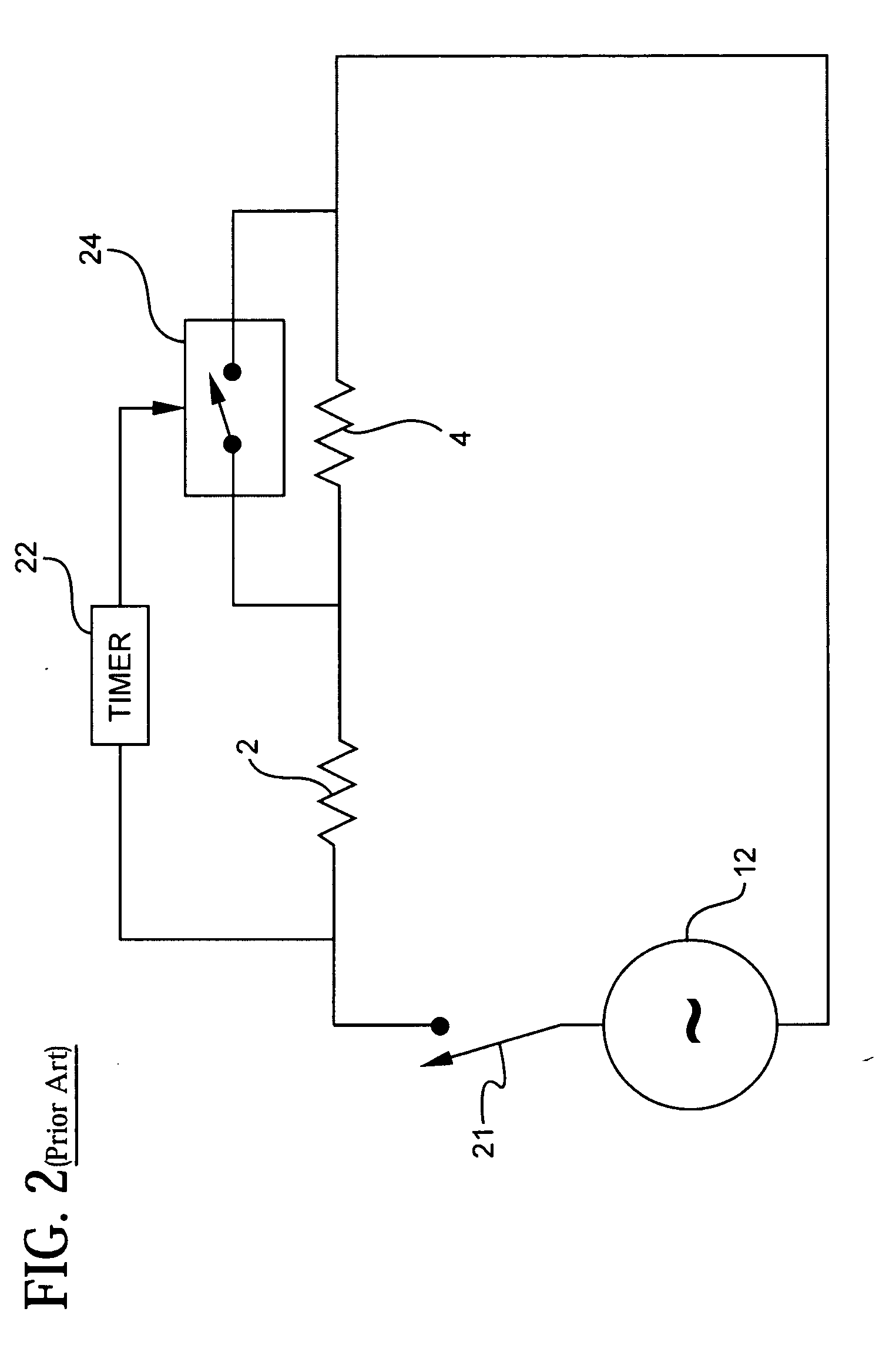
[0038]FIG. 2 illustrates a heater circuit described in U.S. Pat. No. 6,233,397. The heater circuit in FIG. 2 includes the first resistive heating element 2, second resistive heating element 4, power source 12, and a single pole, single throw (SPST) switch 21 connected as a single series circuit. The heater further includes an electrically controllable switch 24.

[0039] The electrically controllable switch 24 includes first and second switch terminals that are electrically connected across the second heating element 4. The electrically controllable switch 24 also includes at least a third control terminal that receives a control signal. In response to the received control signal, the switch terminals open (high resistance) or close (low resistance). The electrically controllable switch 24 may take the form of a solid-state switch or conventional relay. In this circuit configuration, when the switch terminals are closed, the second heater element 4 is bypassed (shorted) in the series c...

fourth embodiment

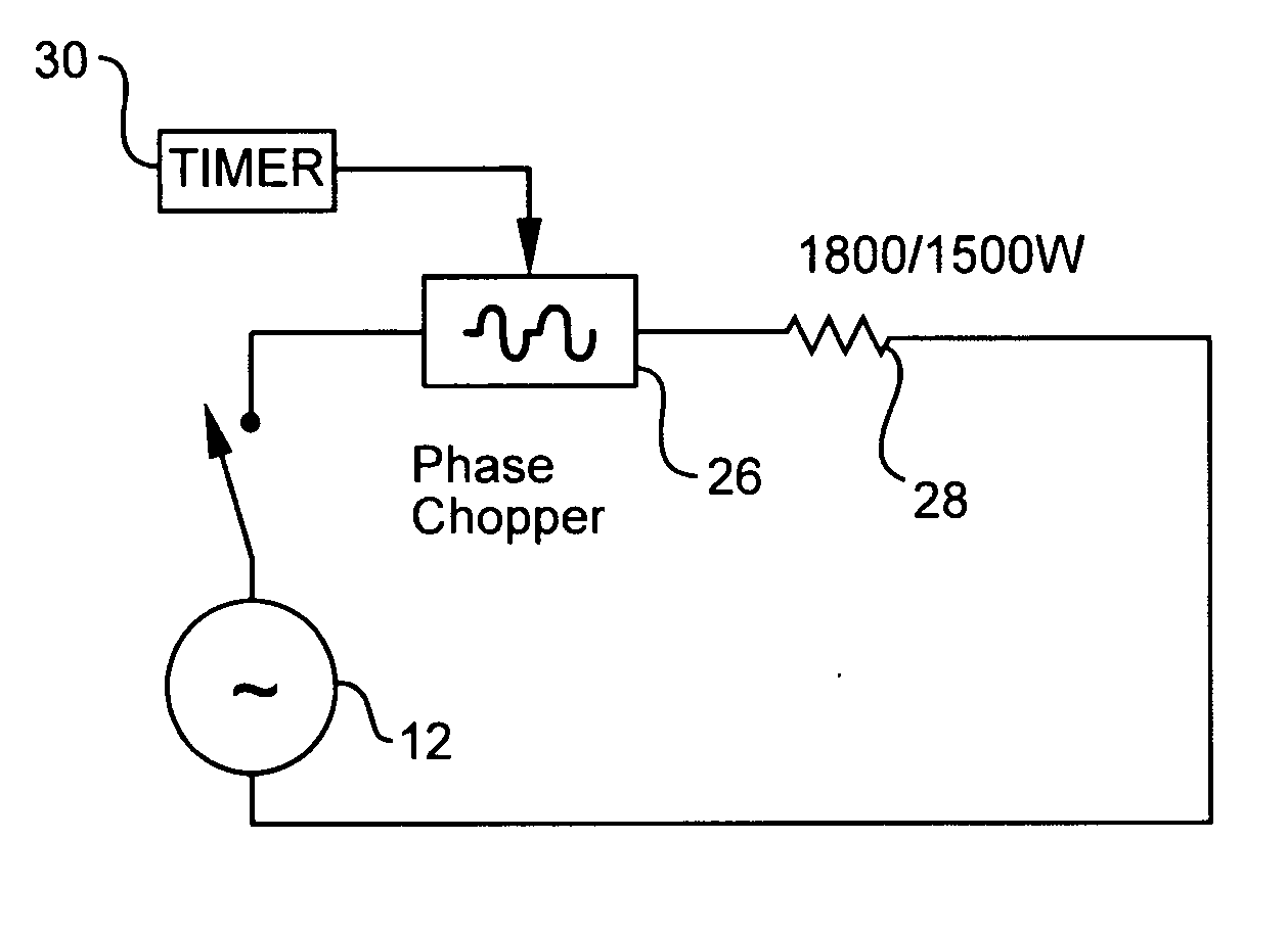
[0046]FIG. 4a shows a two-stage heater circuit formed in accordance with the present invention using a phase chopper circuit 26 connected in series with a resistive heating element 28 capable of providing different power levels. In this embodiment, the power source 12 is preferably connected across the series combination of the heating element 28 and phase chopper circuit 26.

[0047] The phase chopper circuit 26 is preferably implemented using one or more thyristers, triacs, diacs, and / or silicon controlled rectifiers, as described in further detail in U.S. Pat. No. 6,294,874, which is incorporated herein by reference. A timer circuit 30 preferably provides a control signal that controls the phase chopper circuit 26 to trigger at a particular point on the sine curve of the AC power signal provided by the power source 12. The timer circuit 30 is preferably implemented by using an appropriately configured 555 integrated circuit timer or other conventional timing circuit known in the art...


PUM


Abstract

A heater operates at a first power to heat a space and a second power to maintain the temperature. The heater uses a first heating element and a second heating element, which are configured to automatically supply the first power during an initial heating period, then step down to the second power for continuous operation. The heater may use a phase chopper circuit and heating element; switched diode and heating element; positive temperature coefficient thermostat, isolated heater, and heating element; latching mechanical timer switch and heating element; and/or a positive temperature coefficient heating element and multi-speed fan to provide dual power levels. The heater may include a first heating element energized during a portion of a heating cycle and a second heating element continuously energized during the heating cycle. The heating cycle is repeated for a period after which both elements are de-energized.

Description

CROSS REFERENCE TO RELATED APPLICATIONS [0001] This application claims the benefit of U.S. Provisional Application No. 60 / 683,757, filed on May 23, 2005, and U.S. Provisional Application No. 60 / 793,080, filed on Apr. 19, 2006, of the same title, the disclosures of which are incorporated herein by reference.BACKGROUND OF THE INVENTION [0002] 1. Field of the Invention [0003] The present invention relates to electric heaters, and more particularly relates to an electric heater capable of operating at different power levels. [0004] 2. Description of the Related Art [0005] Portable electric heaters are currently limited to a continuous power rating of no greater than 1500 watts. This limit is designed to reduce the risk of fire associated with continuous-use heating devices operating at capacities beyond this power rating. This limit is also enforced by product certification agencies, such as Underwriters Laboratories, and model codes, such as the National Electric Code. [0006] However, ...

Claims


Application Information

Patent Timeline
IPC IPC(8): F24D13/00H05B1/02
CPCH05B1/0275F24H9/2071F24H15/407F24H15/37
Inventor CLARKE, BRIAN D.ASHWORTH, ROBERTCRAWFORD, JOHN LEECROSSMAN, SEANHOOVER, RANDALL CLAYTONTHRASHER, CHARLES THOMAS JR.XU, DANNY
Owner SUNBEAN PROD INC
Why Eureka
Try Eureka