Image forming apparatus and control method of image forming apparatus

a technology of image forming and control method, which is applied in the direction of electrographic process apparatus, printing, instruments, etc., can solve the problems of color deviation, color misregistration, and requiring new downtime, and achieve high-precision misregistration detection and increase cost

Inactive Publication Date: 2006-11-23
CANON KK
View PDF1 Cites 15 Cited by
  • Summary
  • Abstract
  • Description
  • Claims
  • Application Information

AI Technical Summary

Benefits of technology

[0013] The present invention has been made in view of the above-described problems, and has as its object to provide a

Problems solved by technology

In an image forming apparatus having a plurality of image forming units, driving unevenness occurs in the device due to factors such as lack of machine accuracy or the like, causing a misregistration (color deviation) in each color.
Particularly in an apparatus having an image forming unit including a laser scanner and a photosensitive drum for each color, if a distance between the laser scanner and the photosensitive drum differs in the image forming units of respective colors, a difference is generated in a laser scanning width on the photosensitive drum, resulting in a color deviation.
However, in detection of the misregistration detection patterns, the result is influenced by uneven driving of the photosensitive drum and uneven driving of the conveying belt

Method used


Image

  • Image forming apparatus and control method of image forming apparatus
  • Image forming apparatus and control method of image forming apparatus
  • Image forming apparatus and control method of image forming apparatus

Examples


first embodiment

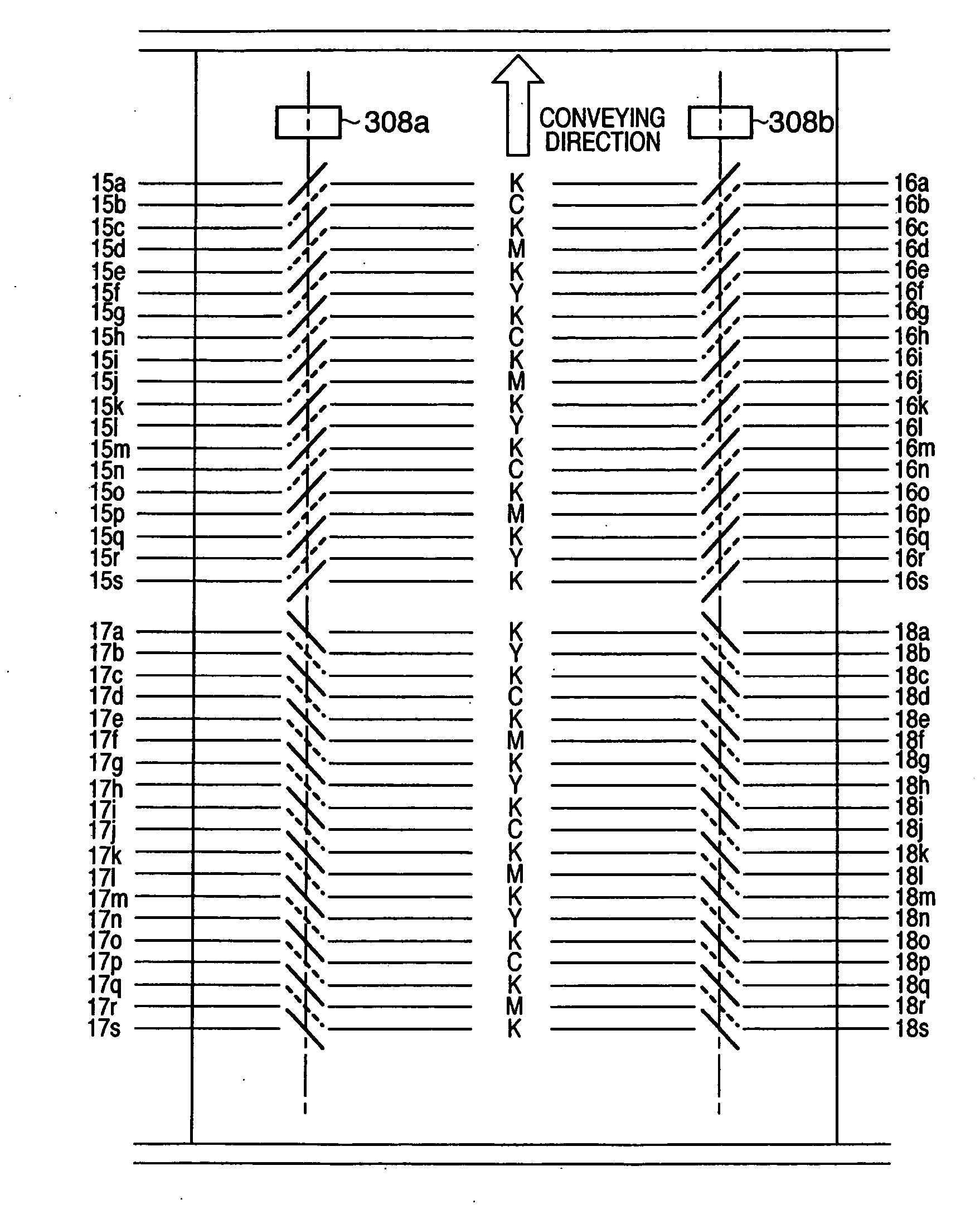
[0069] The first embodiment of an image forming apparatus according to the present invention is described below using, as an example, a case of employing a misregistration detection pattern where the order of detection colors is changed among the patterns having different shapes. Note that since the apparatus configuration and the operation flow are similar to that of the above-described premise art, description thereof is omitted.

Misregistration Detection Pattern According To First Embodiment

[0070]FIG. 9 shows a misregistration detection pattern formed on the conveying belt according to the first embodiment.

[0071] The shape of the basic pattern used in misregistration detection is similar to that of the above-described premise art (FIG. 5). The arranging position of the misregistration detection pattern is also the same.

[0072] More specifically, assume that the reference letters are defined as follows:

[0073] Distance between patterns having an identical detection color and an ...

second embodiment

[0095] The second embodiment of an image forming apparatus according to the present invention is described below using, as an example, a case of employing a misregistration detection pattern where the order of detection colors is changed among the patterns having an identical shape. Note that since the apparatus configuration and the operation flow are similar to that of the above-described premise art, description thereof is omitted.

[0096] In the image forming apparatus according to the present embodiment, assume that the peripheral length of the driving roller 307 of the conveying belt 306 is 48 mm, and the peripheral length of the photosensitive drum 303 is 40 mm. The assumed driving unevenness includes driving unevenness caused by the driving roller 307 and driving unevenness caused by the photosensitive drum 303. Assume that the maximum value of the driving unevenness caused by the driving roller 307 is 60 μm, and the maximum value of the driving unevenness caused by the photo...

third embodiment

[0123] The third embodiment of an image forming apparatus according to the present invention is described below using, as an example, a case of employing a mountain-shaped pattern as a basic pattern used in misregistration detection. Note that since the apparatus configuration and the operation flow are substantially identical to that of the above-described premise art, description thereof is omitted.

[0124] In the image forming apparatus of the present embodiment, assume that the peripheral length of the driving roller 307 of the conveying belt 306 is 60 mm, and the peripheral length of the photosensitive drum 303 is 30 mm. The assumed driving unevenness includes driving unevenness caused by the driving roller 307 and driving unevenness caused by the photosensitive drum 303. Assume that the maximum value of the driving unevenness caused by the driving roller 307 is 60 μm, and the maximum value of the driving unevenness caused by the photosensitive drum 303 is 40 μm. Further, assume...


PUM


Abstract

This invention enables an image forming apparatus to perform highly precise misregistration detection without causing increased downtime or increased cost. For this, the image forming apparatus according to the invention comprises a detection unit for detecting a misregistration detection pattern formed on an endless belt. The employed misregistration detection pattern includes a first pattern array formed with a misregistration detection color or a reference position color, and a second pattern array formed with a misregistration detection color or a reference position color. The misregistration detection pattern is configured in a way that the first pattern and the second pattern have different shapes, and that the color order of the first patterns in the first pattern array and the color order of the second patterns in the second pattern array are different.

Description

FIELD OF THE INVENTION [0001] The present invention relates to a misregistration detection technique in image forming of an image forming apparatus. BACKGROUND OF THE INVENTION [0002] In an image forming apparatus having a plurality of image forming units, driving unevenness occurs in the device due to factors such as lack of machine accuracy or the like, causing a misregistration (color deviation) in each color. Particularly in an apparatus having an image forming unit including a laser scanner and a photosensitive drum for each color, if a distance between the laser scanner and the photosensitive drum differs in the image forming units of respective colors, a difference is generated in a laser scanning width on the photosensitive drum, resulting in a color deviation. [0003] In view of this, there is a technique for making various adjustments to correct the misregistration. That is, misregistration detection patterns are formed on a conveying belt, then the positions of the misregi...

Claims


Application Information

Patent Timeline
IPC IPC(8): G03G15/01
CPCG03G15/0131G03G2215/0161G03G2215/0119
Inventor HAYAKAWA, MASAHIRO
Owner CANON KK
Why Eureka
Try Eureka