High frequency incision tool for endoscope

a high-frequency incision and endoscope technology, applied in the field of high-frequency incision tools for endoscopes, can solve the problems of compromising patient safety, affecting patient safety and affecting the safety of patients

Active Publication Date: 2006-11-23
KANEKA CORP
View PDF11 Cites 71 Cited by
  • Summary
  • Abstract
  • Description
  • Claims
  • Application Information

AI Technical Summary

Benefits of technology

[0039] According to the high frequency incision tool for endoscope of the invention, since the tip of at least one of the electrode blades is provided with a planar portion with a projected area, when viewed from the front, larger than the cross sectional area of the electrode blade at a portion close to its front end, the front end of the incision tool can be protruded from a treatment tool guide lumen of an endoscope into the body in a safe

Problems solved by technology

However, the above-mentioned related high frequency incision tool for endoscope has a problem that at the beginning of use, when the front end of the incision tool protrudes from the treatment tool guide lumen of the endoscope into the body, the tip of the thin electrode blade may violently press and damage the surface the mucous membrane, or even puncture the mucous membrane at worst.
Although the use of cup-like electrode blades of bawl-shaped biopsy forceps eliminates such a problem, such a cup of the bawl-like electrode blade b

Method used


Image

  • High frequency incision tool for endoscope
  • High frequency incision tool for endoscope
  • High frequency incision tool for endoscope

Examples


first embodiment

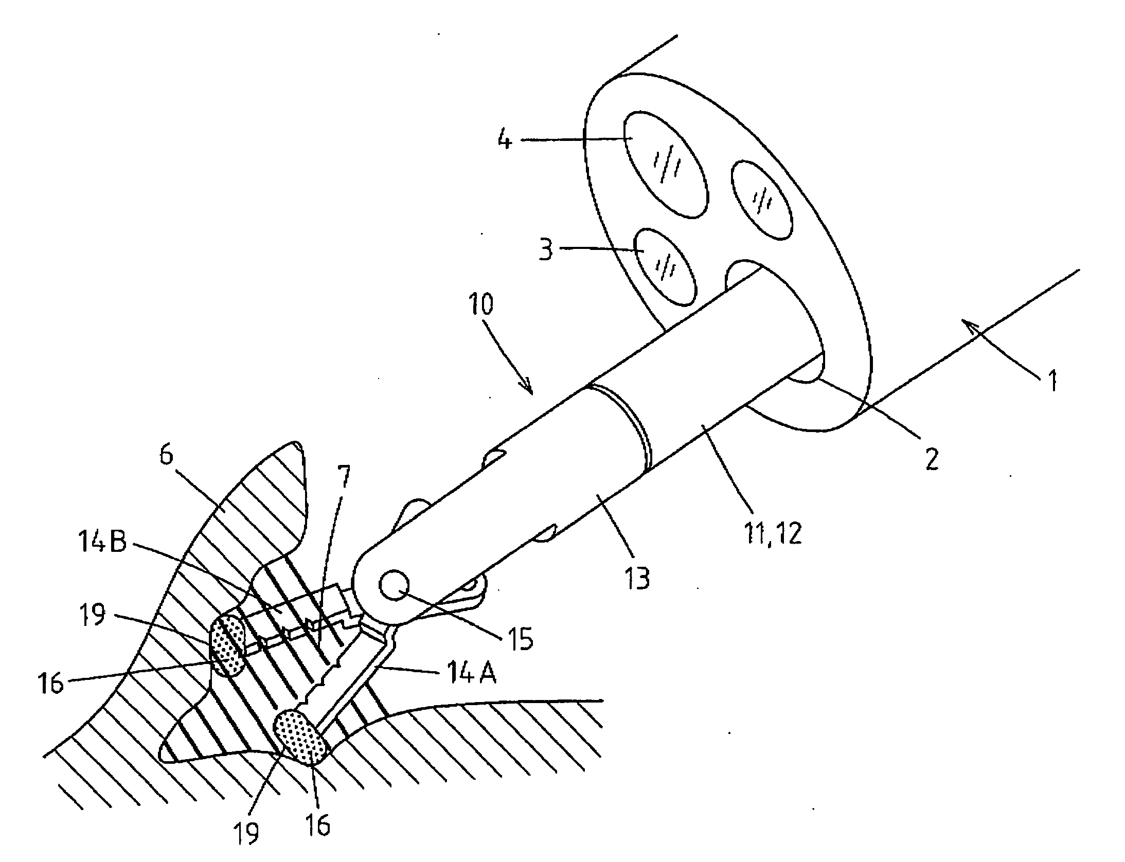
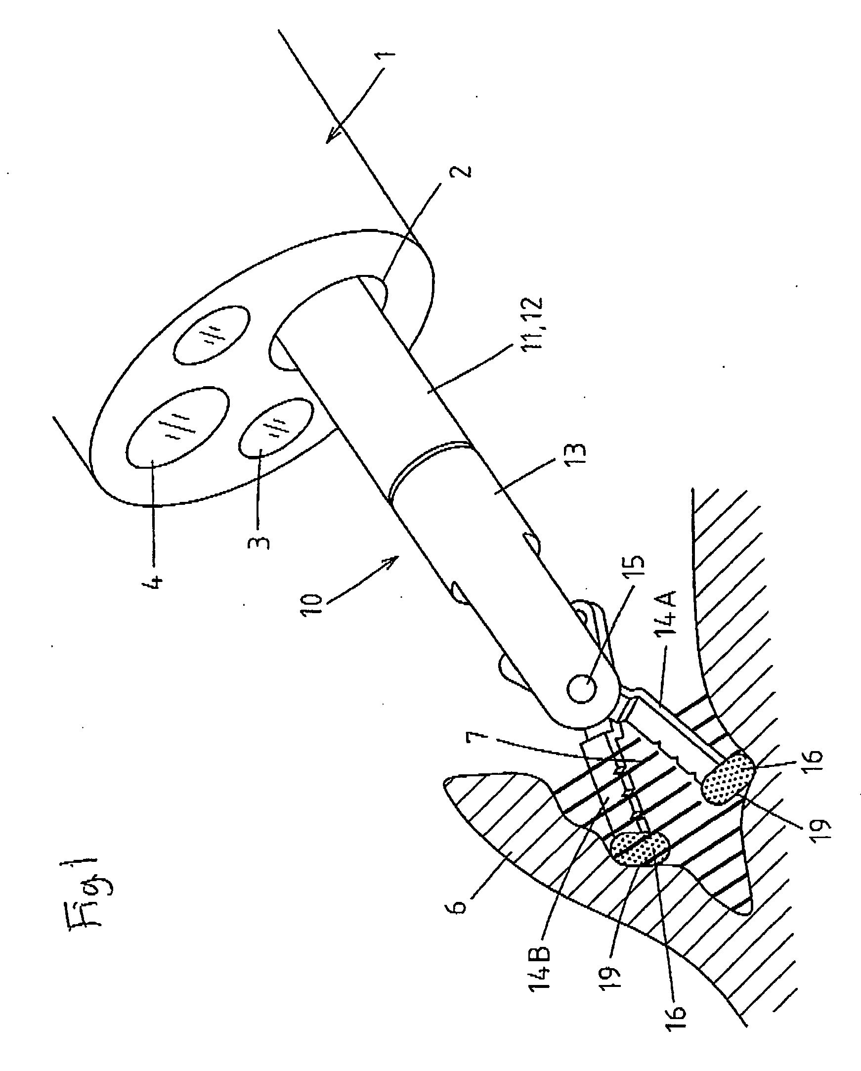
[0072] Embodiments of the invention will be specifically described hereinafter with reference to the drawings. FIG. 1 shows a state that a high-frequency incision tool 10 of the invention is inserted through a treatment tool guide lumen 2 of an endoscope 1 and a front end portion of the high-frequency incision tool 10 protrudes from the treatment tool guide lumen 2 into a body cavity of a patient. This process is illuminated by illumination light radiated from an illumination window 3 of the endoscope 1 and endoscopically observed through an observation window 4.

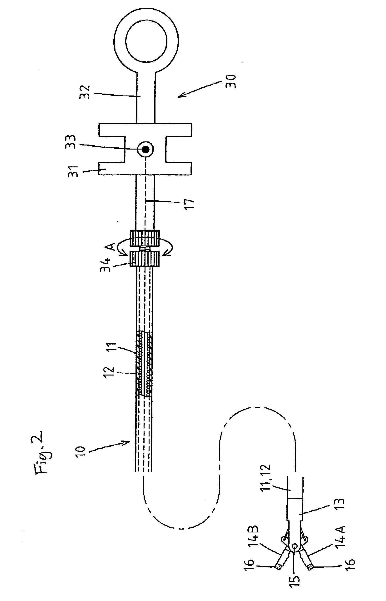
[0073] The portion of the high-frequency incision tool 10 that is inserted through and extracted from the treatment tool guide lumen 2 is constructed in such a manner that a flexible sheath 11 is coated with a casing tube 12 formed of a flexible, electrically insulating tube, through which an operation wire formed of a conductive stainless steel wire or the like is inserted. A front support member 13 is fixedly connected to...

second and third embodiment

[0081]FIGS. 6 and 7 show the front end portion of the high-frequency incision tool 10 according to second and third embodiments of the invention. Each of the electrode blades 14A and 14B deviates sideways from the extension of the center axis line of the front end portion of the front support member 13 and each of the tip portions of the electrode blades 14A and 14B bends sideways (inward) to form an L-shape. Thus configured electrode blades 14A and 14B are easier to manufacture.

[0082] In the second embodiment shown in FIG. 6, the insulating coating 16 encloses the portion of each of the electrode blades 14A and 14B that is distal from the bent position. In the third embodiment shown in FIG. 7, the insulating coating 16 encloses not only the portion of each of the electrode blades 14A and 14B that is distal from the bent position but also the portion backward therefrom. As shown in the figures, the insulating coating 16 only needs to enclose the tip portion of each of the electrode...

fourth embodiment

[0083]FIG. 8 shows that the front end portion of the high-frequency incision tool 10 according to a fourth embodiment of the invention protrudes from the treatment tool guide lumen 2 of the endoscope 1 to perform high-frequency incision (or coagulation). The pair of the electrode blades 14A and 14B in this embodiment is formed such that a half side of a cup of known bawl-shaped metal biopsy forceps is cut and the half-cut bawls face to each other, as shown in FIG. 9, the side view, and FIG. 10, the cross-sectional view taken along the line A-A shown in FIG. 9.

[0084] In this configuration again, at the tip of each of the electrode blades 14A and 14B is formed a curved planar portion 19 that has a larger projected area, when viewed from the front, than the cross-sectional area of each of the electrode blades 14A and 14B at a portion close to its front end. This allows the electrode blades to be protruded into the body cavity without damaging the mucous membrane 6 and mechanically pus...


PUM


Abstract

A high-frequency incision tool for endoscope comprises a sheath inserted through and extracted from a treatment tool guide lumen of an endoscope; an operation unit connected to the rear of the sheath; a pair of electrode blades disposed in parallel and oriented forward at the front position of the sheath, the pair of electrode blades opening forward and closing back through remote manipulation of the operation unit; and a planar portion provided at the tip of at least one of the electrode blades, the planar portion having a projected area, when viewed from the front, larger than the cross sectional areas of the electrode blades at a portion close to their front ends.

Description

BACKGROUND OF THE INVENTION [0001] The present invention relates to a high frequency incision tool for endoscope for use through a treatment tool guide lumen of an endoscope. [0002] High frequency incision tools for endoscope are available in various shapes depending on applications. As an example used for separation of mucous membranes, JP-A-2003-299667 discloses an incision tool including scissors-like electrodes in which a pair of electrode blades disposed in parallel and oriented forward at the front position of a sheath can be remotely opened and closed from the rear end of the sheath. [0003] However, the above-mentioned related high frequency incision tool for endoscope has a problem that at the beginning of use, when the front end of the incision tool protrudes from the treatment tool guide lumen of the endoscope into the body, the tip of the thin electrode blade may violently press and damage the surface the mucous membrane, or even puncture the mucous membrane at worst. Alt...

Claims


Application Information

Patent Timeline
IPC IPC(8): A61B18/14
CPCA61B18/1445A61B2017/2945A61B2018/1497A61B2018/1432A61B2018/00083A61B18/1442A61B18/1492A61B2017/2825A61B2017/2926A61B2018/146
Inventor NISHIMURA, MIYUKI
Owner KANEKA CORP
Why Eureka
Try Eureka