Eureka AIR delivers breakthrough ideas for toughest innovation challenges, trusted by R&D personnel around the world.

Electronic control unit

a control unit and electronic technology, applied in the direction of electrical apparatus, casings with connectors and pcbs, electrical apparatus, etc., can solve the problems of increasing the number of components, reducing the efficiency of the production process, and reducing the manufacturing cost. , the effect of simplifying the production process

Inactive Publication Date: 2011-12-01
MITSUBISHI ELECTRIC CORP
View PDF10 Cites 40 Cited by
  • Summary
  • Abstract
  • Description
  • Claims
  • Application Information

AI Technical Summary

Benefits of technology

The present invention has been made to solve problems with the conventional electronic control unit described above, and aims at providing an electronic control unit in which manufacturing costs can be reduced by simplifying the production process, heat dissipation capability can be enhanced, and as a result, reduction in the size and weight of the unit can be realized.
In an electronic control unit according to the present invention, its assembly process can be simplified because no screws are used in assembling the enclosure, the manufacturing costs can be reduced thanks to reduction in process, and heat dissipation capability per unit board area can be enhanced, so that an electronic control unit can be provided in which reduction in the size and weight thereof can be realized.

Problems solved by technology

A large current can flow through such electronic circuits, which may sometimes lead to breakdown of the circuits and components thereof, unless appropriate countermeasures are taken for dissipating heat.
However, when heat is dissipated by introducing such a structure as described above, the unit is assembled using screws so as to secure close contact between a thermally conductive thin film layer and the metal enclosure, which has therefore caused problems of the number of components increasing and the production process becoming complicated.

Method used


Image

  • Electronic control unit
  • Electronic control unit
  • Electronic control unit

Examples


embodiment 1

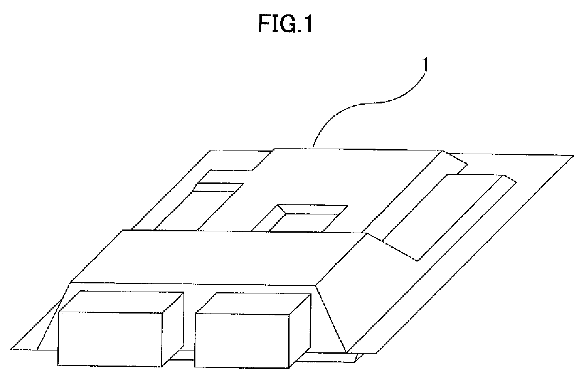
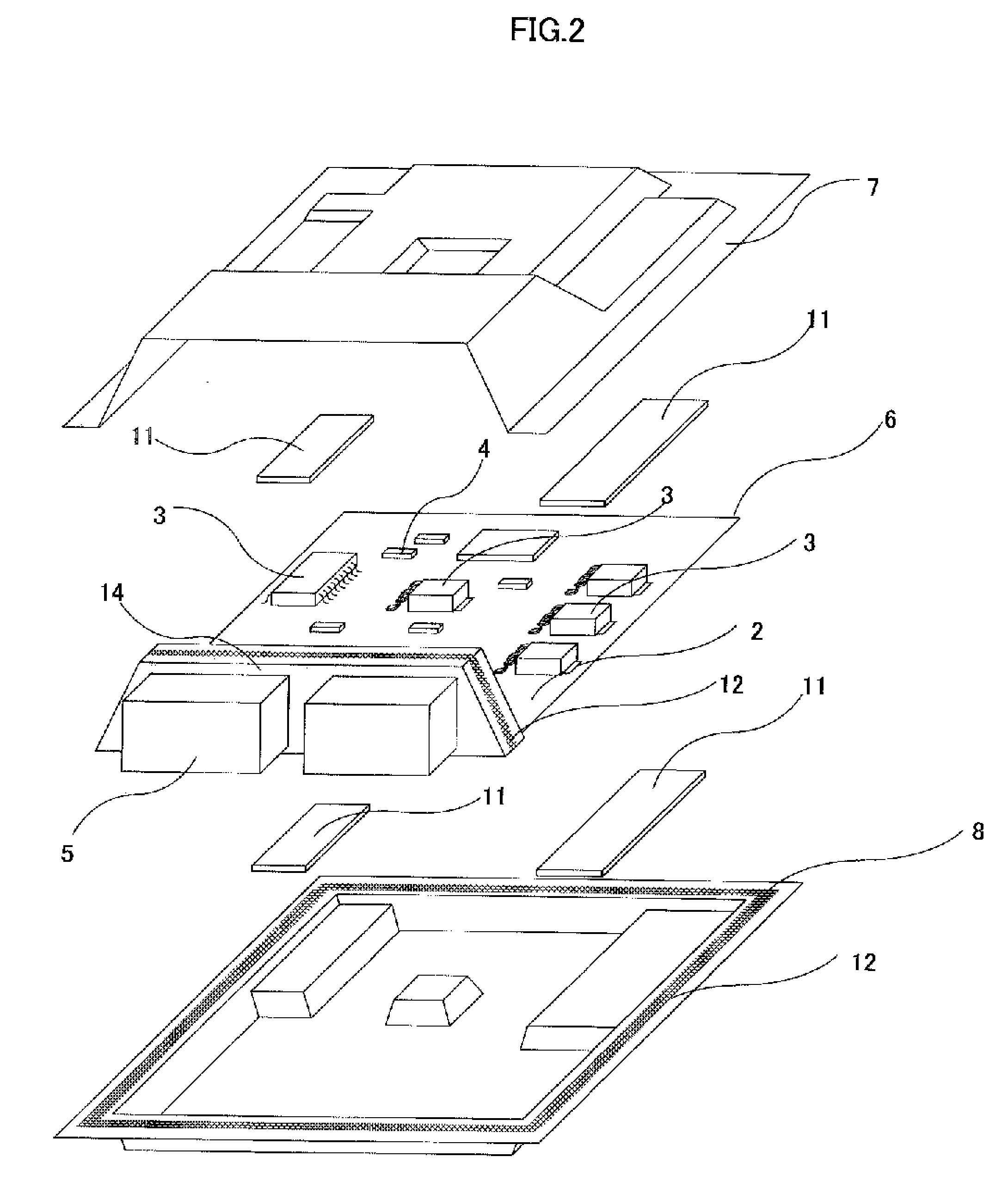
Hereinafter, an electronic control unit according to Embodiment 1 of the present invention will be explained in detail referring to FIG. 1 to FIG. 7. In each drawing, the same reference numeral denotes the same or corresponding part.

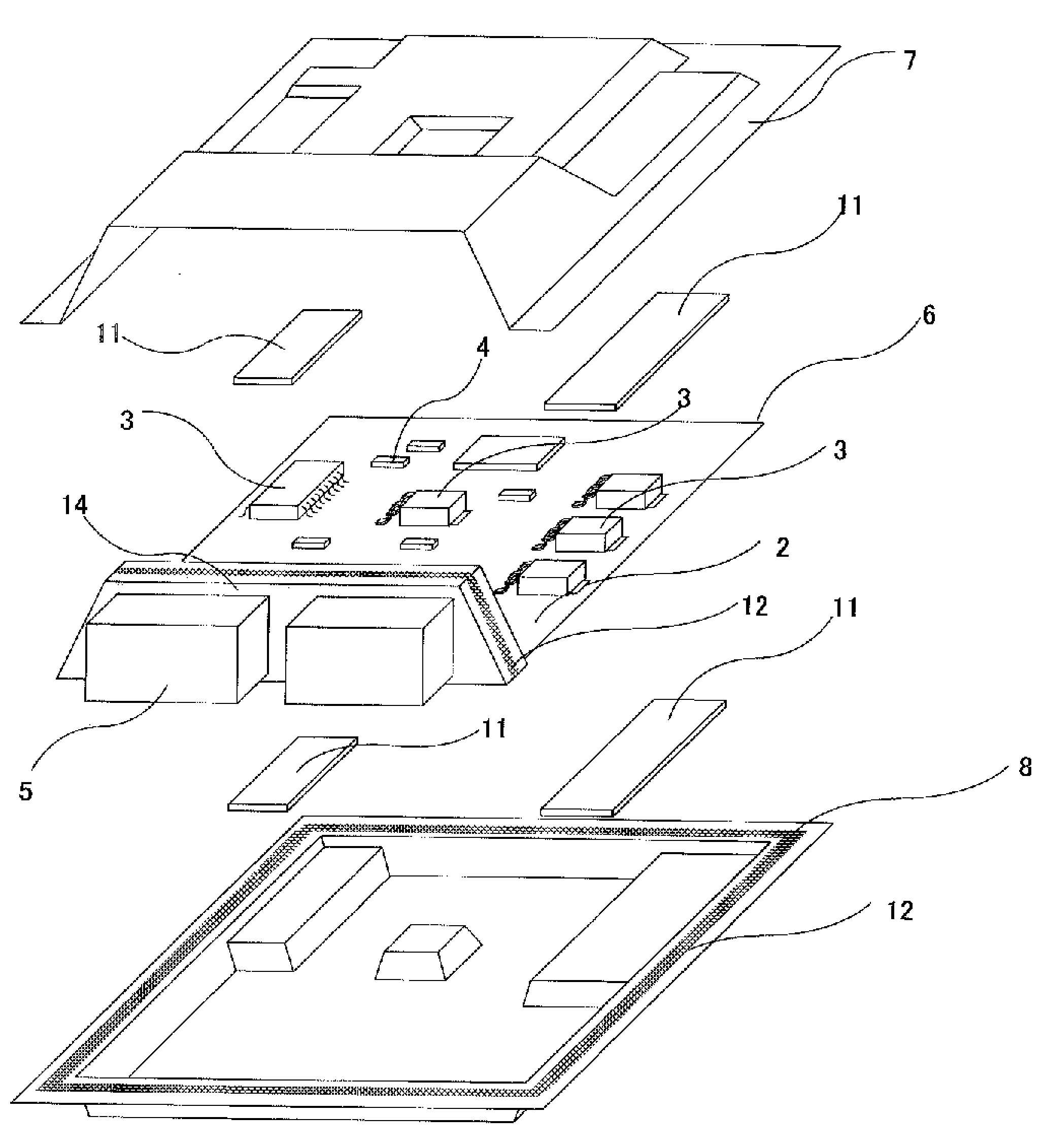
FIG. 1 is a perspective view showing the external appearance of the electronic control unit (hereinafter referred to also as an ECU) 1; FIG. 2 is an exploded perspective view schematically showing the internal structure of the electronic control unit. As shown in FIG. 2, in the ECU 1, a plurality of heat-generating electronic components (hereinafter referred to also as heat-generating components) 3 and other electronic components 4 are mounted on an electronic circuit board (hereinafter simply referred to as a board) 2. Furthermore, in order to connect the ECU 1 with other input / output units (not shown in the figure), a connector 5 provided with a connector holding member 14, which is integrated together with the connector or a separate piece, is mounted...


PUM


Abstract

An electronic control unit includes an electronic circuit board mounted with a plurality of electronic components disposed in a scattered manner on one or both surfaces of the board and at least one connector, and the electronic circuit board is housed in an enclosure made up of enclosure members including a cover and a base, wherein the electronic control unit is structured in such a way that intermediate members each are disposed on both top face of a part of or all of the electronic components and their projected area on the opposite mount surface of the board, portions of the enclosure members are made to closely contact the intermediate members so that both surfaces of the electronic circuit board are sandwiched by the enclosure members and the intermediate members, and edge portions in the periphery of the electronic circuit board are sandwiched by the enclosure members.

Description

FIELD OF THE INVENTIONThe present invention relates to an electronic control unit in which electronic components are mounted on an electronic circuit board (printed circuit board) and the board is housed in an enclosure.DESCRIPTION OF THE RELATED ARTAn electronic control unit (hereinafter referred to also as an ECU; used for controlling a motor vehicle and the like is generally structured in such a way that components constituting electronic circuits, such as an input / output circuit, a communication circuit, a micro processor and a power supply circuit, are disposed on an electronic circuit board and housed in an enclosure.Those electronic components constituting the ECU generate heat depending on their circuit operations. A large current can flow through such electronic circuits, which may sometimes lead to breakdown of the circuits and components thereof, unless appropriate countermeasures are taken for dissipating heat.Therefore, various countermeasures for the heat dissipation h...

Claims


Application Information

Patent Timeline
IPC IPC(8): H05K5/00
CPCH05K5/006H05K5/0052H05K7/20854H05K7/20436
Inventor TANAKA, TAKAAKITAKAHASHI, YASUHIROKUBO, TORUKATO, SEIJIMITANI, MASAKOUMEMOTO, HIDEKI
Owner MITSUBISHI ELECTRIC CORP
Why Eureka
Eureka Blog
Learn More