Detection device

a detection device and detection technology, applied in the direction of mechanical roughness/irregularity measurement, instruments, and reradiation, etc., can solve the problems of non-desired driving control hanging over to the vehicle, and problems that are frequen

Inactive Publication Date: 2006-11-23
SANYO ELECTRIC CO LTD
View PDF7 Cites 70 Cited by
  • Summary
  • Abstract
  • Description
  • Claims
  • Application Information

AI Technical Summary

Benefits of technology

[0007] An object of the present invention is to provide a detection device whi...

Problems solved by technology

In this case, the detection device causes the false detection, and, depending on it, there is the case that non-desired driving contro...

Method used


Image

  • Detection device
  • Detection device
  • Detection device

Examples


Embodiment Construction

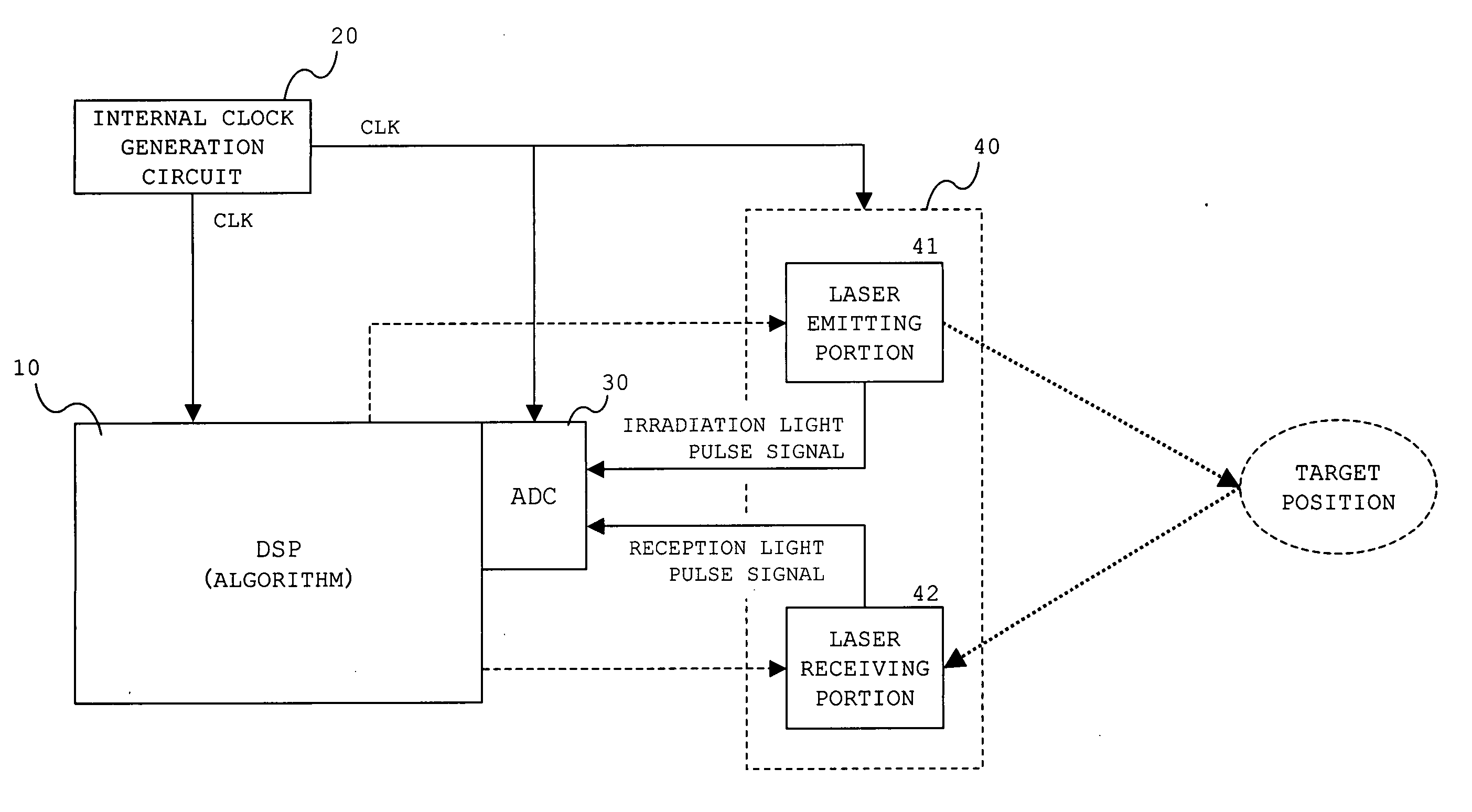
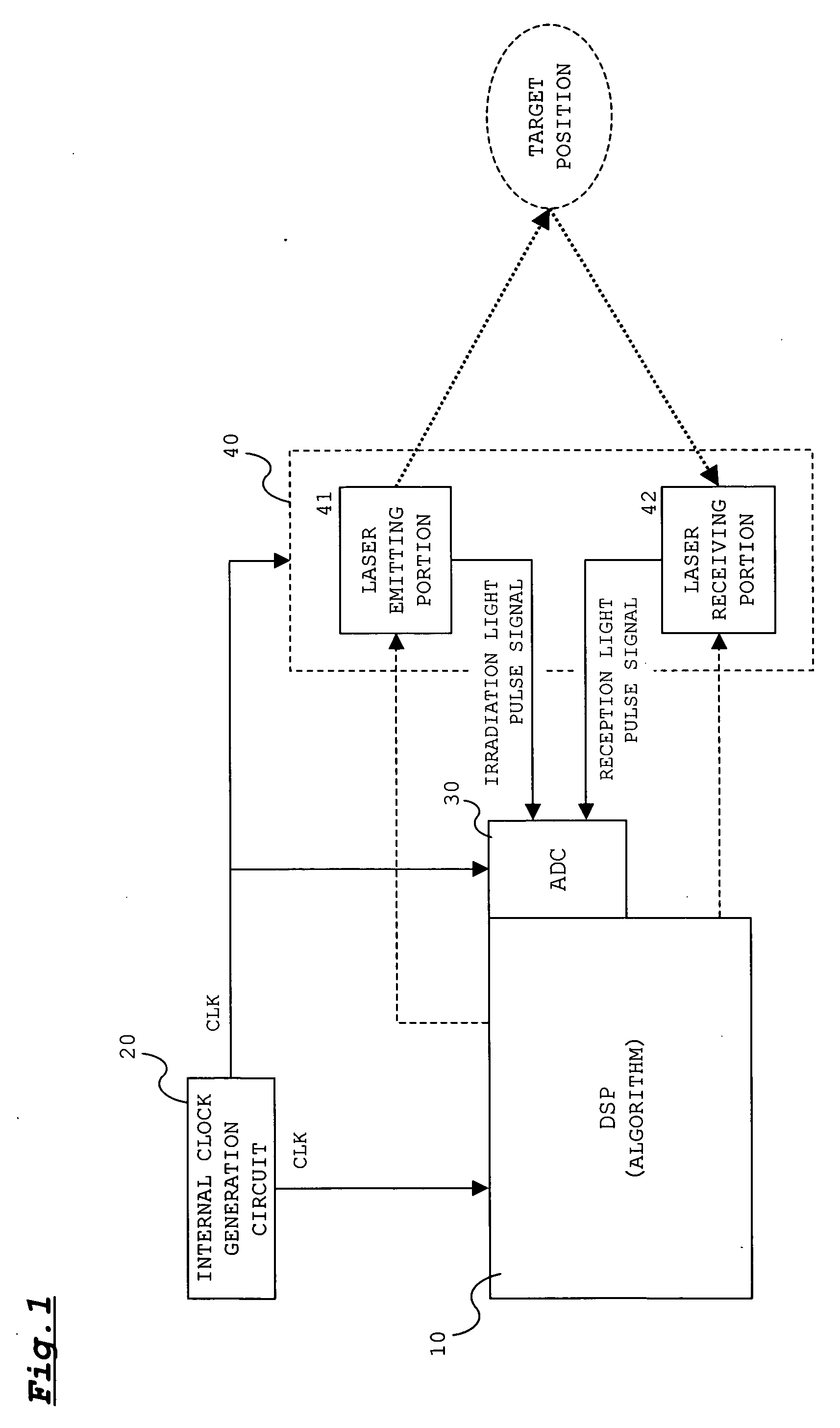
[0029]FIG. 1 shows the configuration of a detection device according to an embodiment of the present invention.

[0030] A beam detection device according to the embodiment is provided with a digital signal processor (DSP) 10, an internal clock generation circuit 20, an analog digital converter (ADC) 30, a beam irradiation device 40.

[0031] The DSP 10 processes irradiation light pulse signals and reception light pulse signals input from a laser emitting portion 41 and a laser receiving portion 42 thorough the ADC 30 to detect the presence or absence of the obstacle at the target position. Also, the DSP 10 counts interval from pulse light emitting timing to pulse light receiving timing referring these signals to measure the distance to the obstacle based on the interval. The processing executed by the DSP 10 will be described later in detail with referring FIG. 6.

[0032] The internal clock generation circuit 20 generates an internal clock of a high frequency and outputs it to the DSP 1...


PUM


Abstract

An object of the present invention is to provide a detection device which does not cause the false detection by receiving laser light from an oncoming car. The pulse laser light modulated with a modulation pattern set every target position is irradiated at the target position from a laser irradiation portion. DSP (Digital Signal Processor) decides that there is an obstacle at the target position only when the modulation pattern of the pulse laser light emitted from the laser emitting portion matches with the modulation pattern of the pulse laser light received by the laser receiving portion. It is suppressed that the detection device misdetects the conditions of the target position when receiving laser light from an oncoming car or the like because modulation pattern of laser light from own does not match with modulation pattern of laser light from the oncoming car or the like.

Description

BACKGROUND OF THE INVENTION [0001] 1. Field of the Invention [0002] The present invention relates to a detection device for detecting conditions at a target position by irradiating a laser light to the target position. [0003] 2. Description of the Related Art [0004] In recent years, in order to improve driving safety, a detection device for detecting an obstacle ahead in a driving direction of a vehicle or the like by emitting a laser light to a target region is mounted, for example, on a family vehicle. The detection device scans a scan surface with a laser light to detect the presence or absence of the obstacle within the scan surface based on the presence or absence of a reflection beam of the laser light. The detection device emits pulse lights at each scan position (target position) to detect the presence or absence of the obstacle at the scan position. At the same time, the distance to the obstacle is measured based on the interval from pulse light emitting timing to pulse lig...

Claims


Application Information

Patent Timeline
IPC IPC(8): G06F19/00G01S7/36G01S7/497G01S17/931
CPCG01S7/481G01S17/936G01S7/497G01S17/931
Inventor YAMAGUCHI, ATSUSHISUZUKIYAMADA, MASATOICHIURA, SHUICHI
Owner SANYO ELECTRIC CO LTD
Why Eureka
Try Eureka