Optical sensor
a technology of optical sensors and optical sensors, applied in the field of optical detection systems, can solve problems such as chromatic aberration, inaccurateness, and angle of view aberration, and achieve the effects of accurate measurement, accurate measurement, and accurate measuremen
- Summary
- Abstract
- Description
- Claims
- Application Information
AI Technical Summary
Benefits of technology
Problems solved by technology
Method used
Image
Examples
embodiment 1
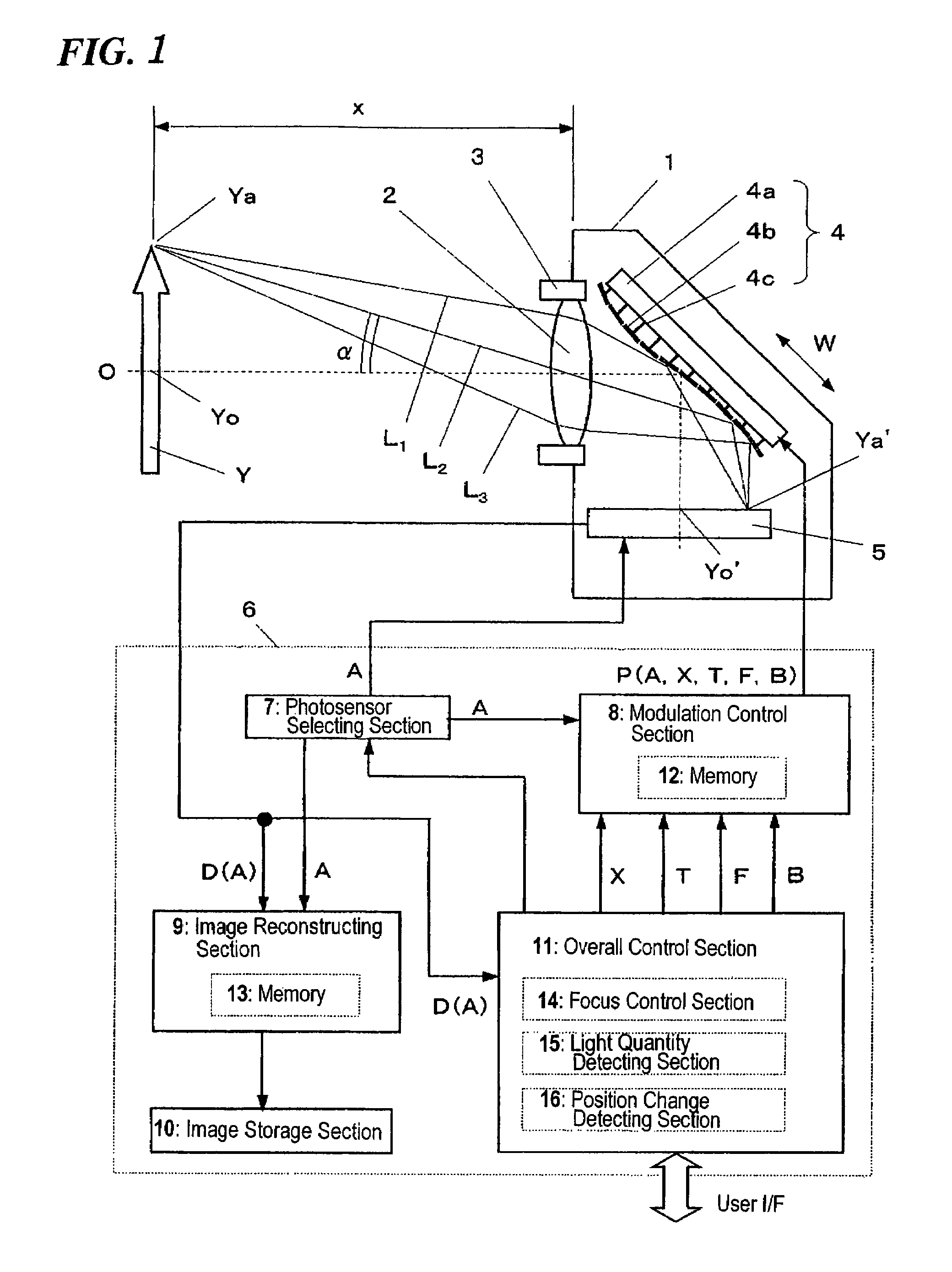
[0056]Hereinafter, an optical detection system according to a first preferred embodiment of the present invention will be described with reference to FIGS. 1 through 6.
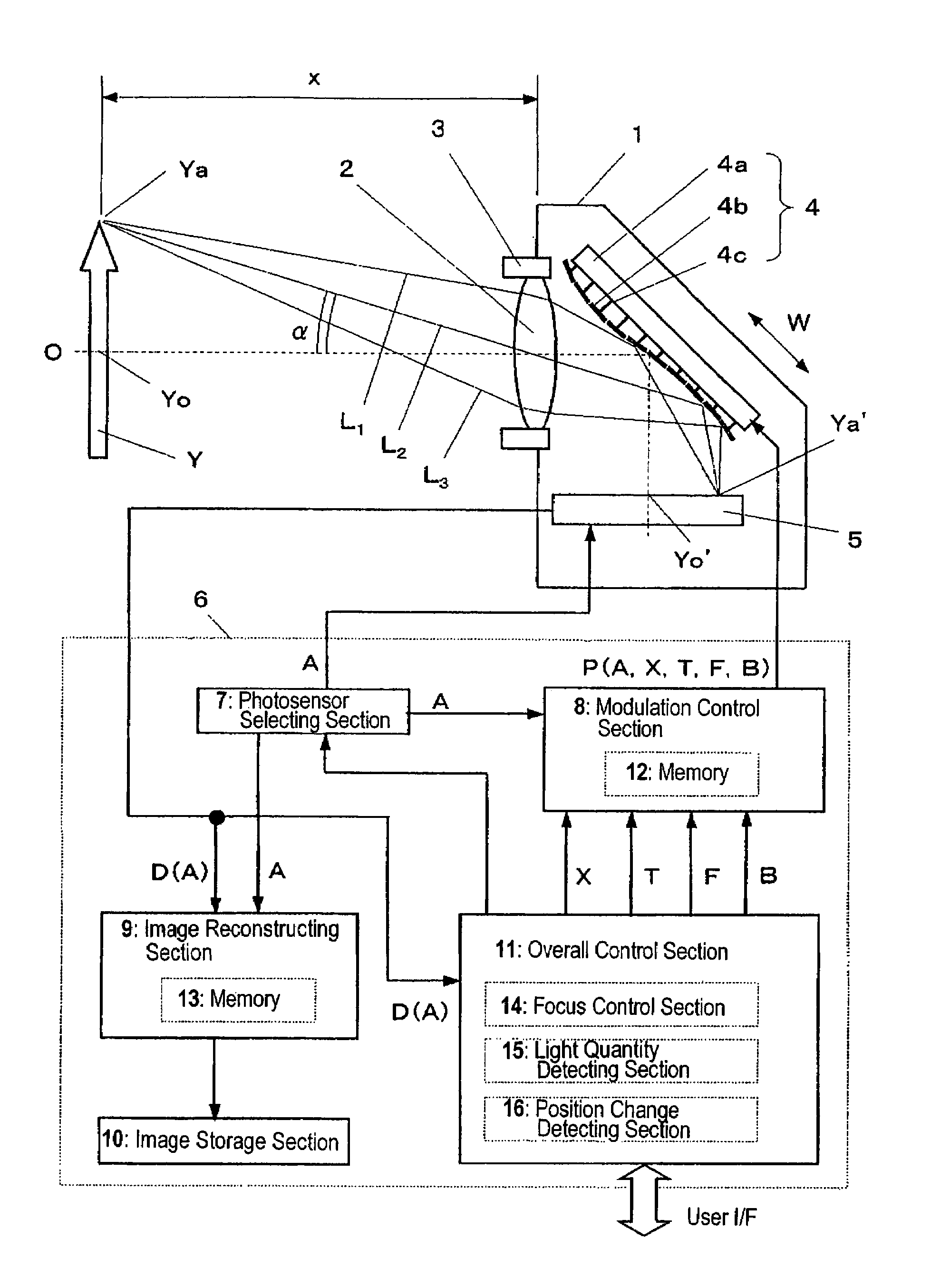
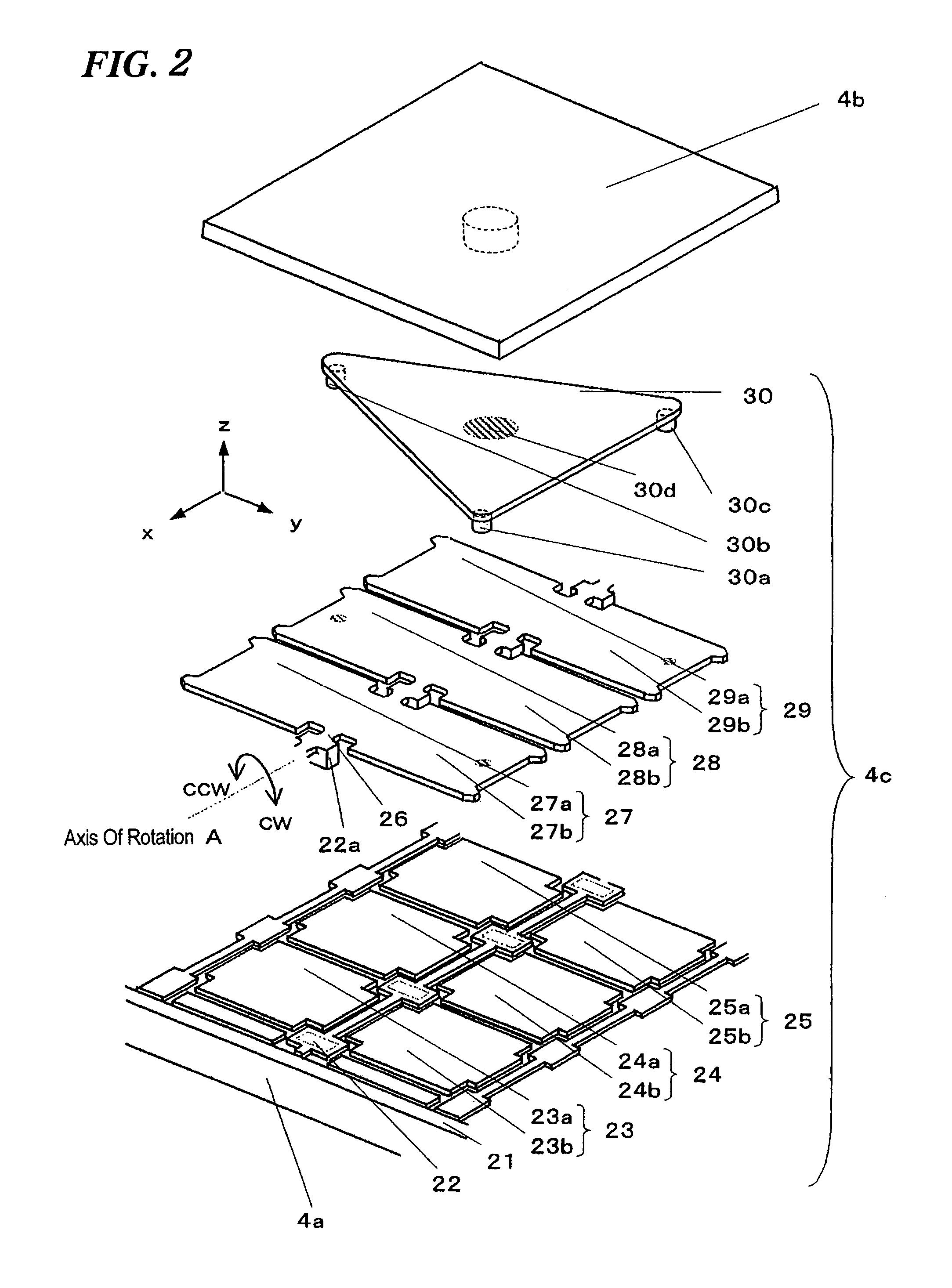
[0057]First, referring to FIG. 1, illustrated is a schematic configuration for an optical detection system according to this preferred embodiment. In the housing 1 of the optical detection system shown in FIG. 1, a lens 2, a lens moving mechanism 3, a deformable mirror 4, a photodetector 5, and a controller 6 are provided. As shown as a block diagram in FIG. 1, the controller 6 includes a photosensor selecting section 7, a modulation control section 8, an image reconstructing section 9, an image storage section 10 and an overall control section 11.
[0058]The lens 2 is an objective lens for condensing the light that has come from an object Y, which is the target to be imaged. After having passed through the lens 2, the incoming light has its phase modulated by the deformable mirror 4 functioning as a spatial light modul...
embodiment 2
[0116]Hereinafter, an optical detection system according to a second preferred embodiment of the present invention will be described with reference to FIG. 7, which illustrates a schematic configuration for an optical detection system according to the second preferred embodiment of the present invention.
[0117]In this preferred embodiment, the deformable mirror 4, a photodetector 55, and a controller 56 are fixed to the housing 51 of the optical detection system. The controller 56 includes a modulation control section 57, the image storage section 10 and an overall control section 58. Also, a replaceable lens unit 52 is mounted on the housing 51. The deformable mirror 4 and image storage section 10 have the same configurations as those already described for the first preferred embodiment.
[0118]The lens unit 52 is provided so as to be attachable to, and removable from, the housing 51 and to be replaceable with another lens unit. In this preferred embodiment, the lens unit 52 includes ...
embodiment 3
[0137]Hereinafter, an optical detection system according to a third preferred embodiment of the present invention will be described with reference to FIG. 8. In this preferred embodiment, portions of the spatial light modulator and photosensor selecting section are implemented as a liquid crystal element and the photodetector is implemented as a photosensitive film. FIG. 8 illustrates a schematic configuration for an optical detection system according to the third preferred embodiment of the present invention.
[0138]In this preferred embodiment, the lens 2, the lens moving mechanism 3, a liquid crystal phase modulator 72, a liquid crystal shutter 73, a photosensitive film 74 and a controller 75 are fixed to the housing 71 of the optical detection system. The controller 75 includes a photosensing selector 76, a modulation control section 77, and an overall control section 78. The lens 2 and lens moving mechanism 3 have the same configurations as those already described for the first p...
PUM
 Abstract
Description
Claims
Application Information
 - R&D
- Intellectual Property
- Life Sciences
- Materials
- Tech Scout
- Unparalleled Data Quality
- Higher Quality Content
- 60% Fewer Hallucinations
Browse by: Latest US Patents, China's latest patents, Technical Efficacy Thesaurus, Application Domain, Technology Topic, Popular Technical Reports.
© 2025 PatSnap. All rights reserved.Legal|Privacy policy|Modern Slavery Act Transparency Statement|Sitemap|About US| Contact US: help@patsnap.com


