
Medication safety system featuring a multiplexed RFID interrogator panel

a technology of interrogator panel and medication safety system, which is applied in the field of programing medical devices, can solve the problems of multiple fluid conduits, attendant risk of typing or entering errors, and attendant risk of incorrect data entry, and achieve the effect of not disabling the pump operation

Active Publication Date: 2006-11-23
CAREFUSION 303 INC
View PDF27 Cites 270 Cited by
  • Summary
  • Abstract
  • Description
  • Claims
  • Application Information

AI Technical Summary

Benefits of technology

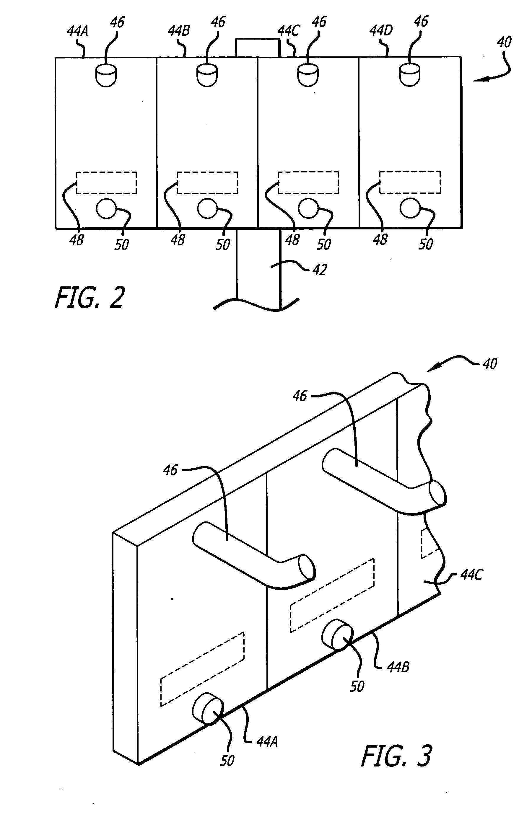
[0027] Yet additional detailed aspects include mounting multiple medication containers to the panel, each medication container having a respective information device, and wirelessly reading each of the information devices with at least one reader mounted in the panel and providing information signals representative of the information contained in each of the information devices. Another aspect comprises multiplexing the multiple information signals representative of the information contained in each of the information devices. Further, the medication safety method comprises wirelessly reading each of the plurality of information devices with multiple readers mounted in the panel and providing a plurality of information signals representative of the information contained in each of the information devices, and multiplexing the multiple information signals representative of the information contained in each of the information devices.
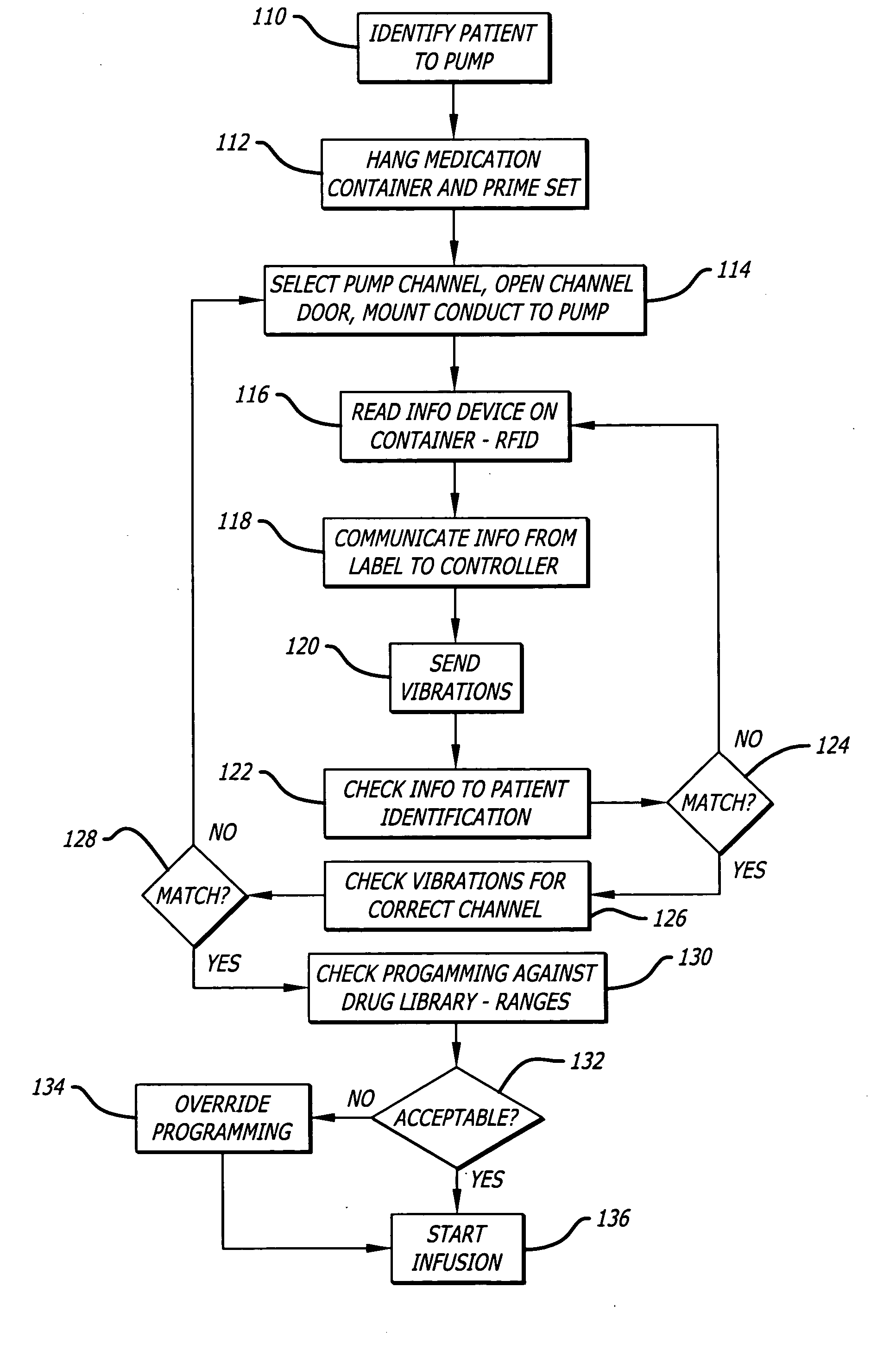
[0028] In further detailed method aspects, the medication safety method further comprises comparing the patient identification information for each of the containers to a patient identified to the pump, and if the identifications do not match, providing an alert. Further, the medication safety method comprises comparing the delivery parameter read from the information device to a data base having an acceptable range for the delivery parameter, and if the delivery parameter contained in the information signal is outside the acceptable range, providing an alert. In further detail, the step of comparing further includes comparing the delivery parameter read from the information device to a data base having an acceptable range in which there is a hard limit and a soft limit, disabling the operation of the pump if the delivery parameter from the information signal exceeds the hard limit, and providing an alert if the delivery parameter from the information signal exceeds the soft limit but does not equal or exceed the hard limit and not disabling the pump from operation. In one aspect, the comparing step is performed at a controller of the medication delivery apparatus, and in another, the comparing step is performed at a location remote from the medication delivery apparatus.

Problems solved by technology

Medical errors, such as when a patient receives the wrong drug or receives the correct drug at the wrong time or in the wrong dosage, are significant concerns for all health care facilities.
While some such systems can provide a significant benefit, others can involve considerable effort by the clinician to: scan the bar code of the patient's identification device; scan the bar code of the clinician's badge; scan the bar code of the infusion system; and scan the bar code of the IV medication container label;
Unfortunately, some skill is required with a bar code system when it is working properly and when it is not working, information must be manually input to the appropriate medical devices by the clinician, with the attendant risk of typing or entry errors.
When the bar code labels become wet with medical fluids, or are otherwise obscured due to one reason or another, they sometimes become unreadable by the bar code scanner then requiring the manual input of their information with its attendant risk of incorrect data entry.
There is the further problem of multiple fluid conduits where multi-channel pumps are involved.
Where there are multiple infusion conduits present, there is a concern that a fluid conduit may be mounted to the wrong infusion pump channel or wrong infusion pump and the drug delivered under incorrect pumping parameters.
As an example, where multiple infusion pump channels are located side by side, there is a concern that a fluid infusion line or conduit may be installed in the wrong pump channel.
Where a more dense infusion pump environment exists, it is important to be sure that the correct medical fluid conduits are being mounted to the correct pump or “channel.” The fluid sources for all pump channels may be suspended immediately above the pump channels and the conduits of the administration sets may become intertwined, thus making it more difficult to select the correct conduit for the particular channel of the pump.
Even though the foregoing have provided significant advances in the art to avoid medication errors and have reduced the likelihood of such medication errors, there still exists some risk that an incorrect bag may become mounted to a pump or pump channel.
Stated differently, there still exists some risk that a bag may become connected to the wrong pump or pump channel.
For example, the nurse could possibly scan the bar code label of the correct bag, but become distracted and mount the conduit of the administration set connected to the bag to the wrong pump channel.
Even if the nurse does not become distracted, the various fluid conduits in a multiple fluid infusion may be difficult to distinguish from one another and tracing the fluid conduit associated with the right bag may become burdensome, especially where the fluid conduits have become tangled with each other.
In such a case, the nurse may inadvertently choose the wrong fluid conduit to install in the pump even after identifying the correct fluid supply.

Method used


Image

  • Medication safety system featuring a multiplexed RFID interrogator panel
  • Medication safety system featuring a multiplexed RFID interrogator panel
  • Medication safety system featuring a multiplexed RFID interrogator panel

Examples


Embodiment Construction

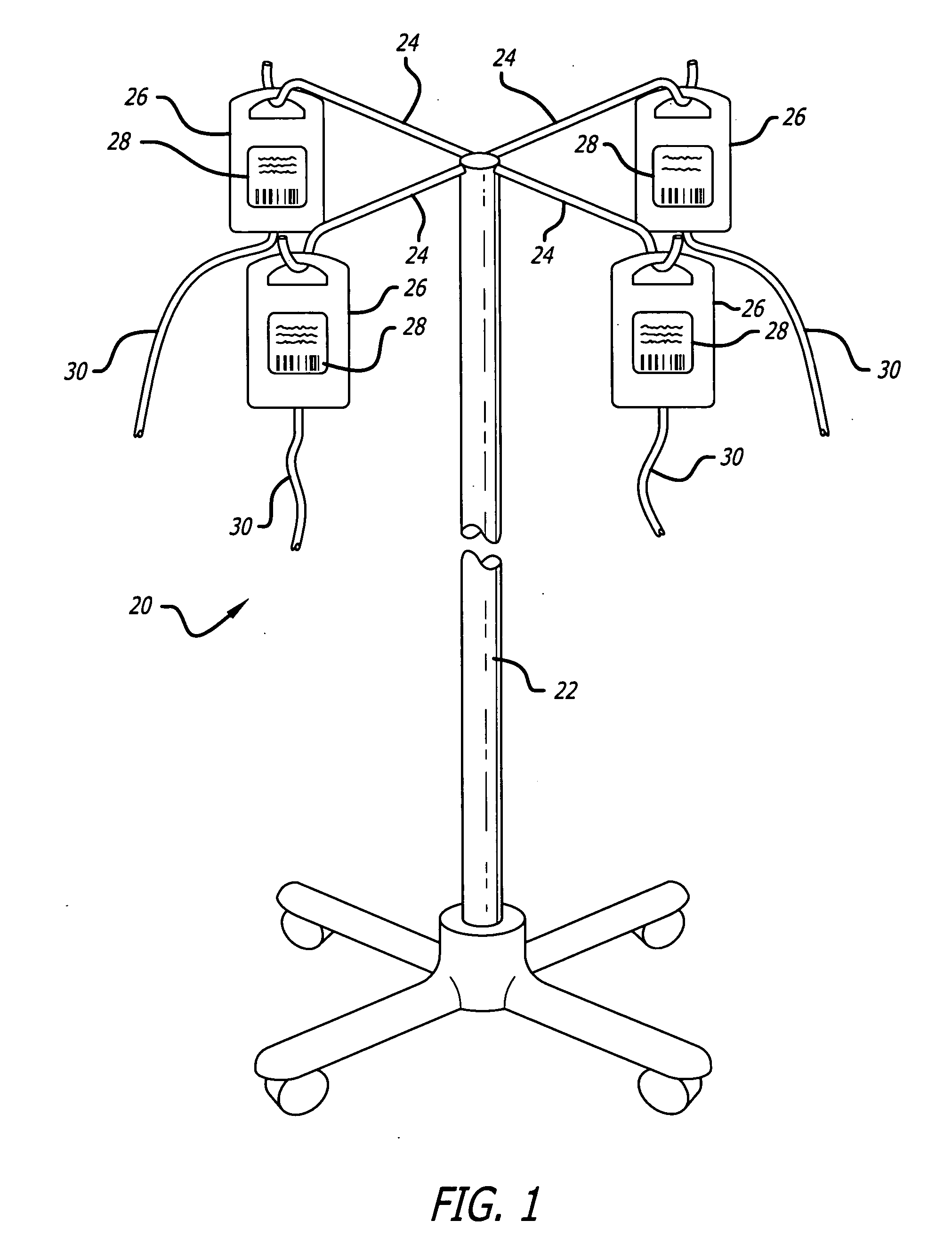
[0036] Referring now in more detail to the drawings in which like reference numerals refer to like or corresponding elements among the several views, there is shown in FIG. 1 an intravenous (“IV”) medication fluid container mounting pole device 20 commonly described as a “coat rack.” The device includes a vertical pole 22 with multiple hanger branches 24 at the top from which articles may be hung. In this case, medication containers 26 would be hung from the hanger branches, the contents of which would be infused to a patient or patients through gravity or with other means such as a volumetric infusion pump (not shown). The pump and patient would be lower than the bags of medication. In using the coat rack with prior systems, information devices 28 on the medication containers would be scanned by a bar code scanner either before the bag is hung on the coat rack or after. This requirement for scanning can cause the problems discussed in the background section to arise. For example, a...


PUM


Abstract

A medication safety system includes a panel mounted to an IV pole above a multi-channel infusion pump also mounted to the IV pole. The panel includes multiple RFID readers for reading the RFID tags placed on each of the medication containers mounted to the panel. The pump includes a controller that communicates with the RFID readers at the panel to receive the information read by the RFID readers and automatically program the respective pump channel. A verification program verifies that the medication delivery information from the containers matches the patient identified for the pump and the programming parameters of the pump fall within acceptable ranges. In another aspect, the panel contains multiple vibration devices to impart vibrations to the medication of each of the containers mounted to the panel. Those vibrations are sensed by the particular pumping channel to confirm that the correct channel has been programmed for that medication. When the clinician opens the door of the pumping channel, the pump may request information from the RFID reader at the panel for that medication and may wait for receipt of the vibrations in the medication of the tubing mounted into the channel.

Description

CROSS-REFERENCES TO RELATED APPLICATIONS [0001] This application claims the benefit of U.S. Provisional Application No. 60 / 679,347, filed May 10, 2005.BACKGROUND OF THE INVENTION [0002] The present invention relates generally to programming medical devices, and more particularly, to a system and a method for automatically verifying the medication to be infused into the patient. [0003] Physicians and other medical personnel apply intravenous (“IV”) infusion therapy to treat various medical complications in patients. IV infusion therapy typically involves infusing medical fluids, such as drugs or nutrients, from a fluid supply, such as a bag, bottle, or other container, through the tube, or conduit, of a fluid administration set (“IV set”) to a cannula inserted into a patient's blood vessel. In a typical healthcare facility, a physician enters an order for medication for a particular patient. This order may be handled either as a simple prescription slip, or it may be entered into an ...

Claims


Application Information

Patent Timeline
Patent Type & Authority Applications(United States)
IPC IPC(8): G06Q10/00G16H20/17G16H40/60
CPCA61B2019/448A61M5/1413A61M5/14212A61M2205/3569G06Q50/22A61M2205/58A61M2205/6018G06F19/3468A61M2205/3592A61B90/98G16H40/60G16H20/17
Inventor HOAG, ROBERT E.
Owner CAREFUSION 303 INC
Learn More