
Method and apparatus for increasing efficiency in use of data bus

a technology of bus and bus clock, applied in the field of bus system, can solve the problems of wasting at least one clock cycle of bus and affecting and achieve the effect of increasing the efficiency of the bus

Inactive Publication Date: 2006-11-23
VIMICRO CORP
View PDF3 Cites 2 Cited by
  • Summary
  • Abstract
  • Description
  • Claims
  • Application Information

AI Technical Summary

Benefits of technology

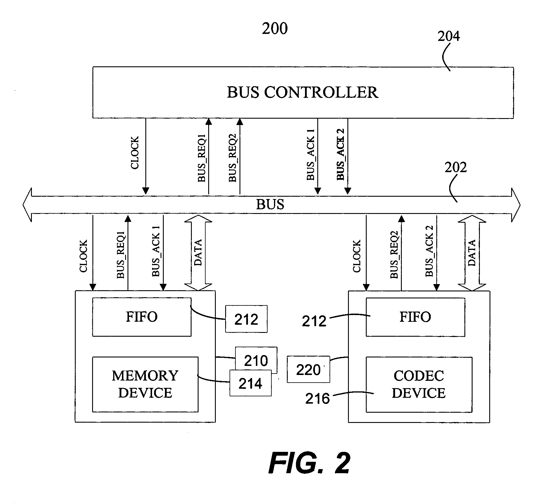
[0009] In general, the present invention pertains to techniques for improving the efficiency of data exchanges over a bus. According to one aspect of the present invention, a bus system includes a bus for transferring data and a device being coupled to the bus for data exchange. The device includes a synchronous memory module providing data required to be transferred and making a bus request for the data transfer over the bus, and a first-in and first-out device (FIFO) coupled between the synchronous memory module and the bus. The FIFO is used to stores the pending data before the bus is granted to the device. The topside data in the FIFO always drives the bus so that the topside data is immediately transferred over the bus once the bus is granted to the synchronous memory module.
[0013] One of the objects, features, and advantages of the present invention is to provide techniques for data exchanges over a bus in order to increase the efficiency in use of the bus.

Problems solved by technology

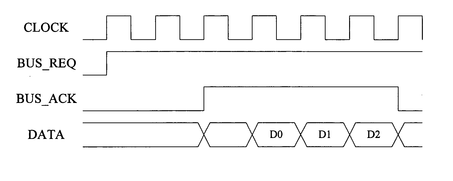
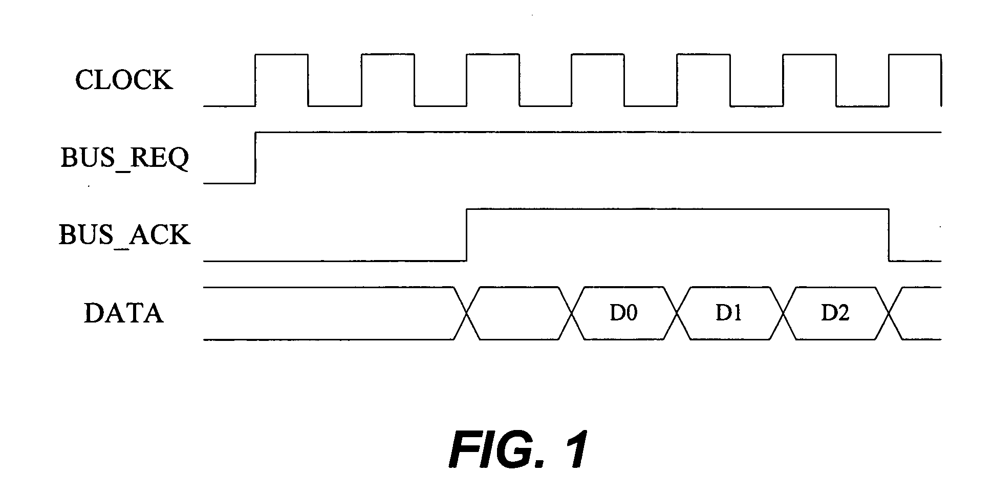
In other words, after the BUS_ACK is sent back to the device or the bus is granted to the device, the device has to delay at least one clock cycle period to start transmitting the data over the bus because the data is required to be latched in a trigger provided in the device before transferred onto the bus, thereby wasting at least one clock cycle of the bus and degradedly affecting the efficiency of the bus.

Method used


Image

  • Method and apparatus for increasing efficiency in use of data bus
  • Method and apparatus for increasing efficiency in use of data bus
  • Method and apparatus for increasing efficiency in use of data bus

Examples


Embodiment Construction

[0019] The detailed description of the present invention is presented largely in terms of procedures, steps, logic blocks, processing, or other symbolic representations that directly or indirectly resemble the operations of devices or systems contemplated in the present invention. These descriptions and representations are typically used by those skilled in the art to most effectively convey the substance of their work to others skilled in the art.

[0020] Reference herein to “one embodiment” or “an embodiment” means that a particular feature, structure, or characteristic described in connection with the embodiment can be included in at least one embodiment of the invention. The appearances of the phrase “in one embodiment” in various places in the specification are not necessarily all referring to the same embodiment, nor are separate or alternative embodiments mutually exclusive of other embodiments. Further, the order of blocks in process flowcharts or diagrams or the use of seque...


PUM


Abstract

Techniques for increasing the efficiency in se of a data bus are disclosed. A bus system includes a bus for transferring data, and a device, being coupled to the bus for data transfer, including a functional module providing data required to be transferred over the bus and a first-in-first-out device (FIFO) coupled between the functional module and the bus. The FIFO is provided to store pending data from the functional module before the bus is granted to the functional portion in responding to a bus request (BUS_REQ) for transferring the data over the bus, wherein topside data in the FIFO always drives the bus so that the topside data is immediately transferred over the bus once the bus is granted to the device or the functional module.

Description

BACKGROUND OF THE INVENTION [0001] 1. Field of the Invention [0002] The present invention relates to a bus system, and more particularly to a functional device coupled to the bus without any accessing latency and a method for data exchange between the functional device and the bus. [0003] 2. Description of Related Art [0004] Most computer based systems include one or more busses for transferring data between functional devices coupled to the busses or between a functional device and an embedded memory coupled to the busses. The function devices coupled to the busses perform dedicated functions and are somewhat autonomous from other devices, though functions performed by these devices usually involve the exchange of data with other devices on the buses. Examples of the function devices include processor, coder, encoder and so on. Such memory typically performs storage function and exchanges data with a functional device, in a sense, that the memory itself is regarded as a functional ...

Claims


Application Information

Patent Timeline
IPC IPC(8): G06F5/00G06F13/16G06F13/38G06F13/42
CPCG06F13/4217G06F13/385G06F13/14G06F13/38
Inventor LIU, JIANZHOU, FENZHOU, TIAN-YI
Owner VIMICRO CORP
Learn More