Refrigerator

a technology of refrigerator and compressor, which is applied in the field of refrigerators, can solve the problems of increasing cost and limit on further improving the efficiency of the refrigerating cycle, and achieve the effects of effective cooling of high-pressure refrigerant pipes, improving the efficiency of the refrigerating cycle, and reducing thermal conductivity

Inactive Publication Date: 2006-11-30
SANYO ELECTRIC CO LTD
View PDF13 Cites 70 Cited by
  • Summary
  • Abstract
  • Description
  • Claims
  • Application Information

AI Technical Summary

Benefits of technology

[0021] According to the aforementioned structure, it is possible to effectively cool the high pressure refrigerant pipe of the refrigerating cycle by using cold energy leaking outside by surrounding the second heat insulating material which has lower thermal co...

Problems solved by technology

However, in the aforementioned conventional structure, there is a limit on further improving the efficiency of the refrigerating ...

Method used


Image

  • Refrigerator
  • Refrigerator
  • Refrigerator

Examples


first embodiment

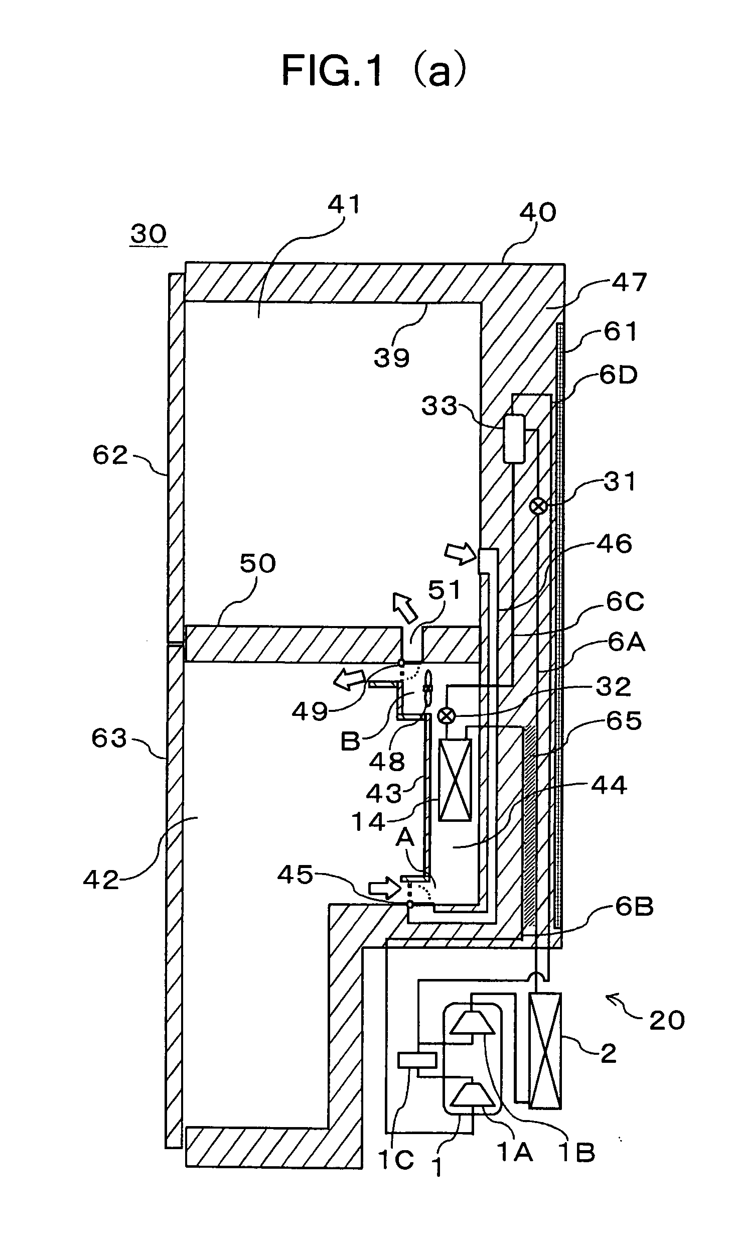
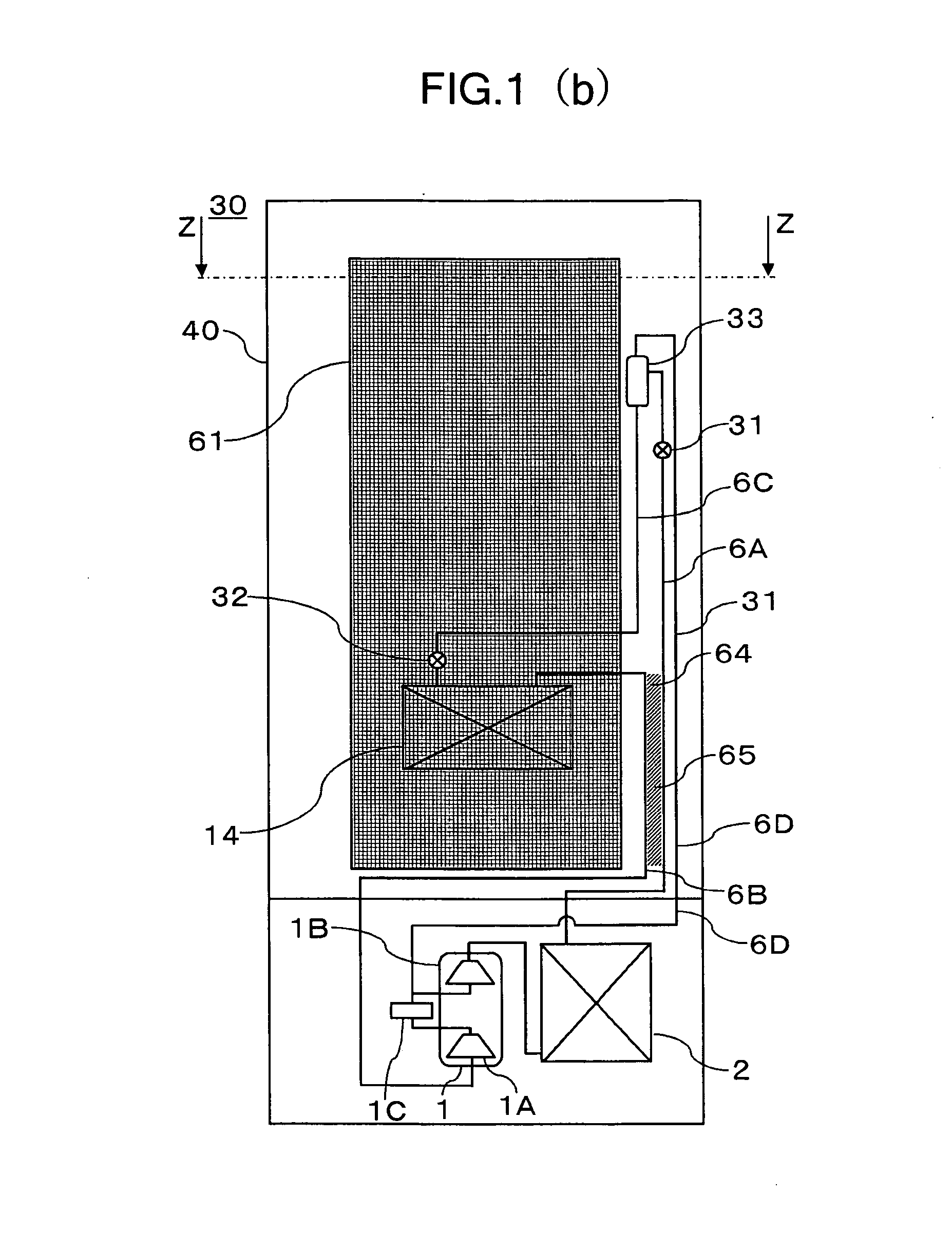
[0030] An embodiment of the present invention is described in detail with reference to the accompanying drawings. FIGS. 1A to 1C are views illustrating an outline structure of a refrigerator 30 according to the present embodiment, wherein FIG. 1A is a side sectional view of the refrigerator 30 according to the present invention, FIG. 1B is a rear elevation of the refrigerator 30, and FIG. 1C is a sectional view, taken along the line Z-Z in FIG. 1B.

[0031] As shown in FIG. 1A, the refrigerator 30 includes a refrigerating cycle unit 20, an outer case 40, an inner case 39, doors 62 and 63, and a middle partition wall 50. A refrigerating compartment 41 and a freezing compartment 42 are formed by partitioning the inner case 39 by using the doors 62 and 63 and the middle partition wall 50.

[0032] The refrigerating cycle unit 20 includes a compressor 1; a radiator 2 connected to the discharge side of the compressor 1; a first expansion valve 31 as decompression means provided in a refriger...

second embodiment

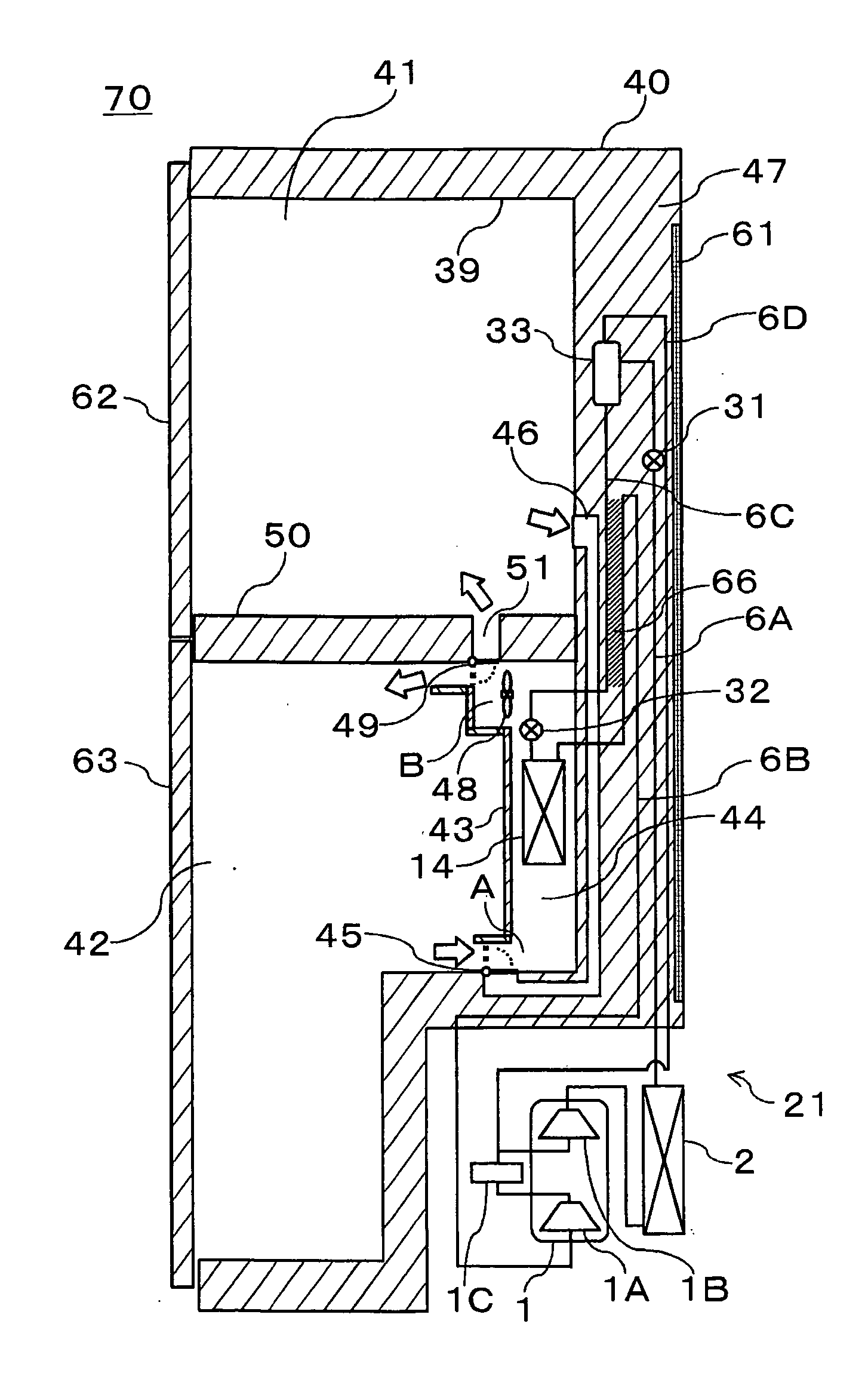
[0070] Next, a second embodiment of the present invention is explained with reference to FIG. 4. FIG. 4 is a side sectional view of a refrigerator 70 of the second embodiment. Incidentally, in FIG. 4, elements which have the same reference numerals as those of the elements in the refrigerator 30 of the first embodiment described above have the same or similar functions and effects as in the first embodiment. When compared to the refrigerator 30 of the first embodiment described above, the refrigerator 70 has a difference in the point in which the refrigerator 70 has a refrigerating cycle device 21 which includes a second heat exchanger 66 instead of the first heat exchanger 65.

[0071] The second heat exchanger 66 is able to conduct heat exchange between the liquid refrigerant separated by the gas-liquid separator 33 and the refrigerant discharged from the heat absorber 14. That is, the second heat exchanger 66 is formed between the refrigerant pipe 6C and the refrigerant pipe 6B. By...

third embodiment

[0072] Next, a third embodiment of the present invention is explained with reference to FIG. 5. FIG. 5 is a side sectional view of a refrigerator 90 of the third embodiment. Incidentally, in FIG. 5, elements which have the same reference numerals as those in each embodiment described above have the same or similar functions and effects as in the first embodiment. When compared to the refrigerator 70 of the second embodiment described above, the refrigerator 90 has a difference in the point in which the refrigerator 90 has a refrigerating cycle device 22 which includes a third heat exchanger 67 in addition to the second heat exchanger 66.

[0073] The third heat exchanger 67 is able to conduct heat exchange between the refrigerant discharged from the radiator 2 and the gas refrigerant separated by the gas-liquid separator 33. That is, the third heat exchanger 67 is formed between the refrigerant pipe 6A and the refrigerant pipe 6D. By using the third heat exchanger 67, in addition to t...


PUM


Abstract

It is an object of the present invention to provide a refrigerator which is able to improve the efficiency of the refrigerating cycle while avoiding causing the structure of the refrigerator to be complicated, and avoiding a cost increase. Refrigerator 30 includes a refrigerating cycle device 20 having a compressor 1, a radiator 2 connected to a discharge side of the compressor 1, a first expansion valve 31 connected to an exit side of the radiator 2, a gas-liquid separator 33 for separating a refrigerant, which is in a mixed gas-liquid state by being decompressed by the first expansion valve 31, into a gas refrigerant and a liquid refrigerant, a heat absorber 14 into which the liquid refrigerant discharged from the gas-liquid separator 33 flows, and a refrigerant pipe 6D for delivering the gas refrigerant discharged from the gas-liquid separator 33 into the middle pressure portion of the compressor 1; an outer case 40; an inner case 39; and a heat insulating material. The gas-liquid separator 33 is arranged in the heat insulating material 47.

Description

BACKGROUND OF THE INVENTION [0001] 1. Field of the Invention [0002] This invention relates to a refrigerator, and in particular, it relates to an improvement of cooling capacity and efficiency in a refrigerator. [0003] 2. Description of the Related Art [0004] In recent years, due to problems such as global warming, there has been a growing demand for the reduction of environmental burdens, and the like, and because of this, a large number of techniques have been proposed for the purpose of reducing electric power consumption and improvement of efficiency in cooling operation for a refrigerator. [0005] For example, Japanese Unexamined Patent Publication No. H11-148761 discloses a technique for improving the efficiency of an operation in a refrigerator by cooling a refrigerating compartment and a freezing compartment alternately and repeatedly to reduce the compression ratio of a compressor. [0006] Furthermore, for the purpose of providing an energy-saving freezing refrigerator by imp...

Claims


Application Information

Patent Timeline
IPC IPC(8): F25D11/02F25B43/00
CPCF25B1/10Y02B40/34F25B40/00F25B2309/06F25B2400/05F25B2400/13F25B2400/23F25D11/02F25D17/045F25D17/065F25D23/006F25D2201/126F25D2201/14F25D2400/04F25B9/008Y02B40/00
Inventor ITSUKI, HIROYUKIMUKAIYAMA, HIROSHIIMAI, SATOSHI
Owner SANYO ELECTRIC CO LTD
Why Eureka
Try Eureka