
On-board light source based gain correction for semi-active laser seekers

a laser seeker and gain correction technology, applied in the direction of instruments, instruments for comonautical navigation, optical radiation measurement, etc., can solve the problems of navigation errors, inability to uniformize the gain or responsivity of detectors, etc., to accurately locate the target direction, improve the accuracy and linearity of the sals, and improve the accuracy and linearity.

Active Publication Date: 2006-11-30
BAE SYST INFORMATION & ELECTRONICS SYST INTERGRATION INC
View PDF4 Cites 7 Cited by
  • Summary
  • Abstract
  • Description
  • Claims
  • Application Information

AI Technical Summary

Benefits of technology

[0006] In one embodiment, the invention provides a method and apparatus for detecting and correcting for relative gain variations among the channels of a semi-active laser seeker (“SALS”). The SALS relies on known gain relationships among the various channels to accurately locate the target direction. Because temperature changes and other effects may change the relative gains between channels, rendering the accuracy and / or linearity of the SALS inadequate, one embodiment of the invention allows for a suitable control system to sense and correct for these relative gain changes, thus restoring accuracy and linearity to the SALS.

Problems solved by technology

But the gain or responsivity is not necessarily uniform between detectors.
This leads to errors in determining the relative amount of energy received at each aperture on the missile, which, in turn leads to errors in navigation.

Method used


Image

  • On-board light source based gain correction for semi-active laser seekers
  • On-board light source based gain correction for semi-active laser seekers
  • On-board light source based gain correction for semi-active laser seekers

Examples


Embodiment Construction

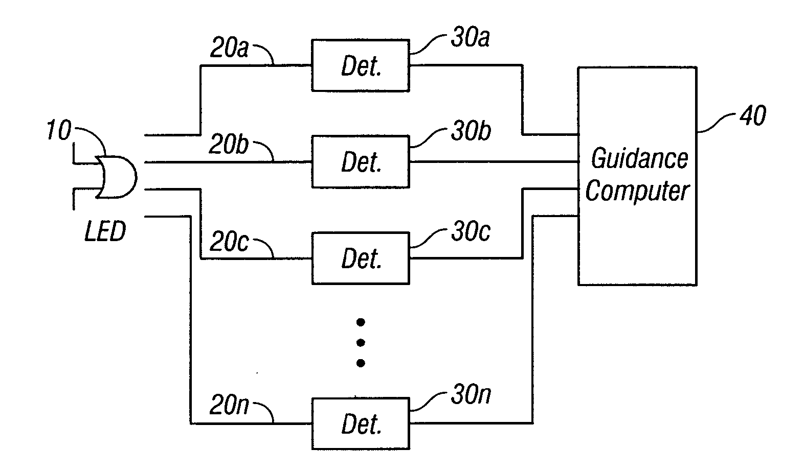
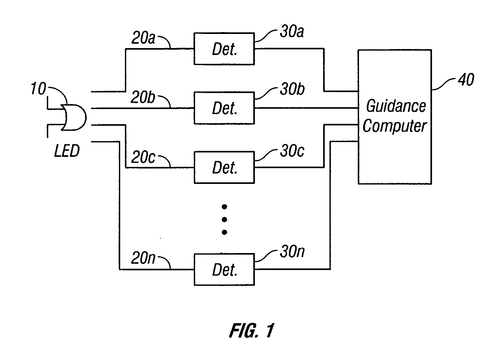
[0012]FIG. 1 shows a block diagram of one embodiment to the invention. In this embodiment the OBLS is an LED 10 which is used to calibrate the responsivity of the detectors. The calibration LED 10 is preferably mounted inside the missile, where it radiates light energy onto a plurality of optical fibers 20a-20n. FIG. 3 depicts the seeker electronics section 12 of a missile according to an embodiment of the invention. In this embodiment, the calibration LED 10 is mounted in the detector board 18 of the seeker electronics 12. Also mounted on the detector board 18 are seven avalanche photodiodes (“APD”) 14, which receive the incoming laser radiation from an external laser designator as well as light from the calibration LED 10. The missile is also provided with back lens plates 16, which contain lenses 15. In one particularly advantageous embodiment the lenses molded into the lens plates for durability. The missile's optical system also includes a front lens plate (not shown), which re...


PUM


Abstract

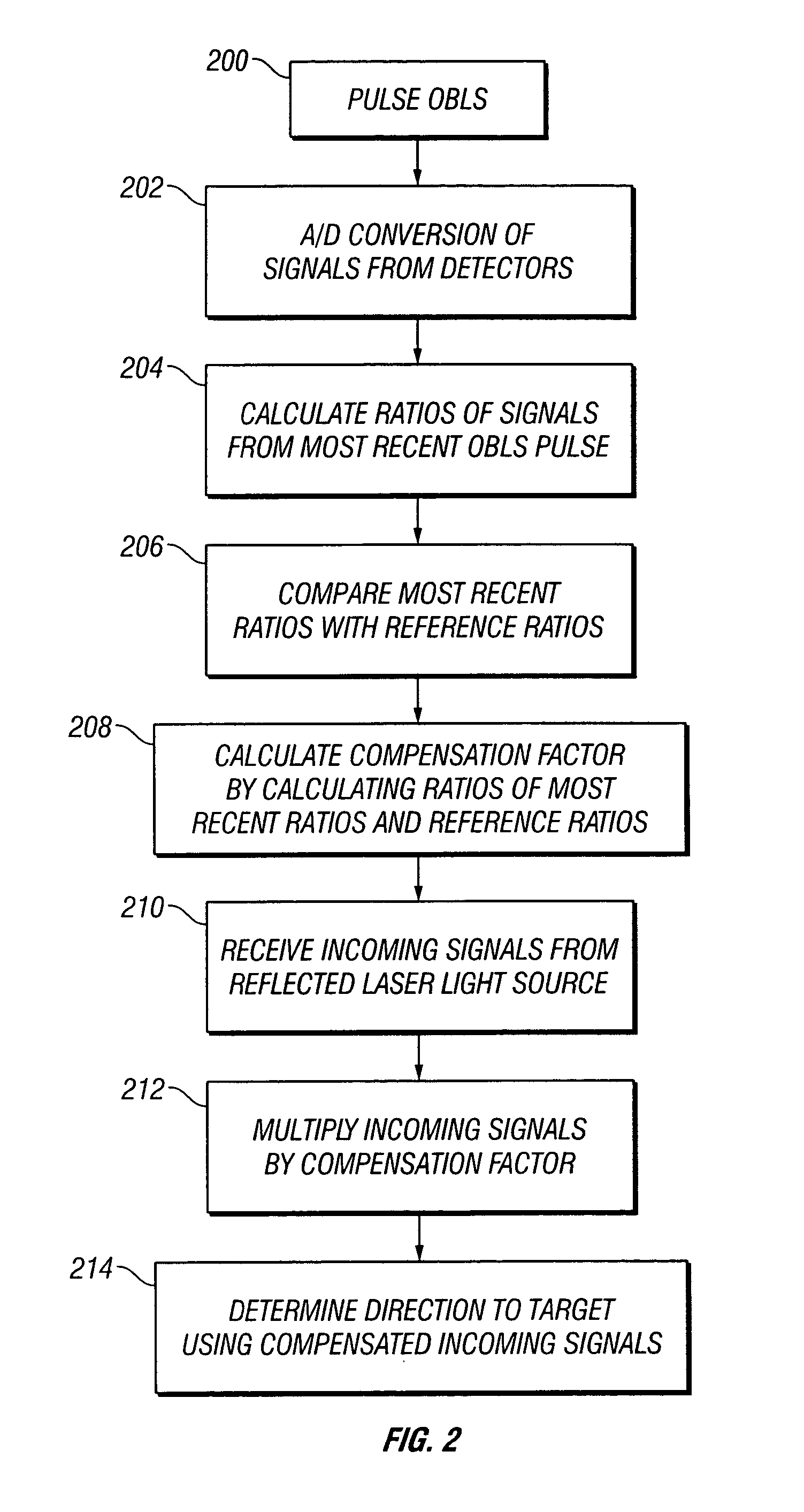
The invention provides a method and apparatus for correcting for gain changes in detectors in a guided vehicle. In one version of the invention, an on board light source is used to generate a reference set of detector gains, which are stored in computer memory. The on board light source is then pulsed at subsequent times and the signals generated by the detectors are compared to the reference set of detector gains to determine whether any gains have changed.

Description

TECHNICAL FIELD [0001] This invention relates generally to guidance systems in self-guiding vehicles. In particular, the invention relates to guided missile systems using lasers to direct guided missiles to their targets. BACKGROUND OF THE INVENTION [0002] Laser guidance systems for controlling guided missiles or other remotely controlled vehicles are known in the art. For example, in a conventional laser guided missile, a laser is used to illuminate the desired target. The laser may be mounted on the missile itself, or may be directed at the target from a separate ground or air-based source. In either case, the laser energy is reflected from the target and detected by the missile. The missile then uses this energy to determine the direction to the target and navigate towards it. [0003] To detect the reflected laser energy, the missile typically has a number of apertures arranged in its nose or other areas on the missile surface. Lenses or other optical components are often located ...

Claims


Application Information

Patent Timeline
Patent Type & Authority Applications(United States)
IPC IPC(8): G01C21/02
CPCF41G7/001F41G7/226F41G7/2293G01S3/7803G01S17/66G01S7/4813G01S7/497G01S17/003G01S3/784
Inventor ALEXANDER, WILLIAM C.SCHORR, DAVID
Owner BAE SYST INFORMATION & ELECTRONICS SYST INTERGRATION INC
Learn More