
Deep ultraviolet light emitting devices and methods of fabricating deep ultraviolet light emitting devices

Inactive Publication Date: 2006-11-30
CREE INC
View PDF99 Cites 22 Cited by
  • Summary
  • Abstract
  • Description
  • Claims
  • Application Information

AI Technical Summary

Benefits of technology

[0006] Some embodiments of the present invention provide light emitting devices and methods of fabricating light emitting devices that emit at wavelengths less than 360 nm with wall plug efficiencies of at least than 4%. In other embodiments, the wall plu

Problems solved by technology

However, to date high efficiency DUV LEDs with emission wavelengths less than approximately 360 nm have not been achieved due to several fundamental technical challenges including the following: output power too low for a given drive current, wallplug efficiency too low, and device lifetime too low.

Method used


Image

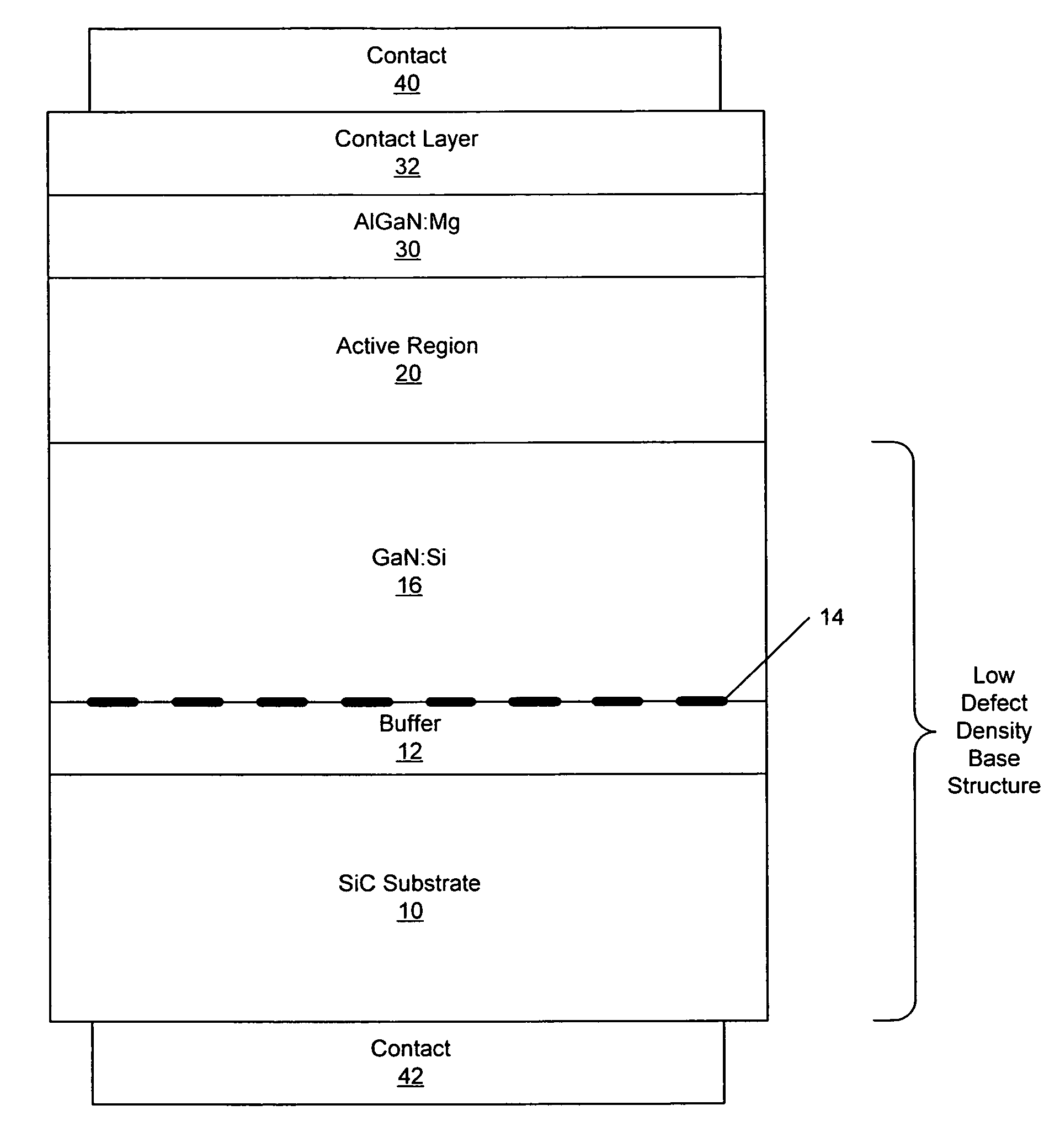
  • Deep ultraviolet light emitting devices and methods of fabricating deep ultraviolet light emitting devices
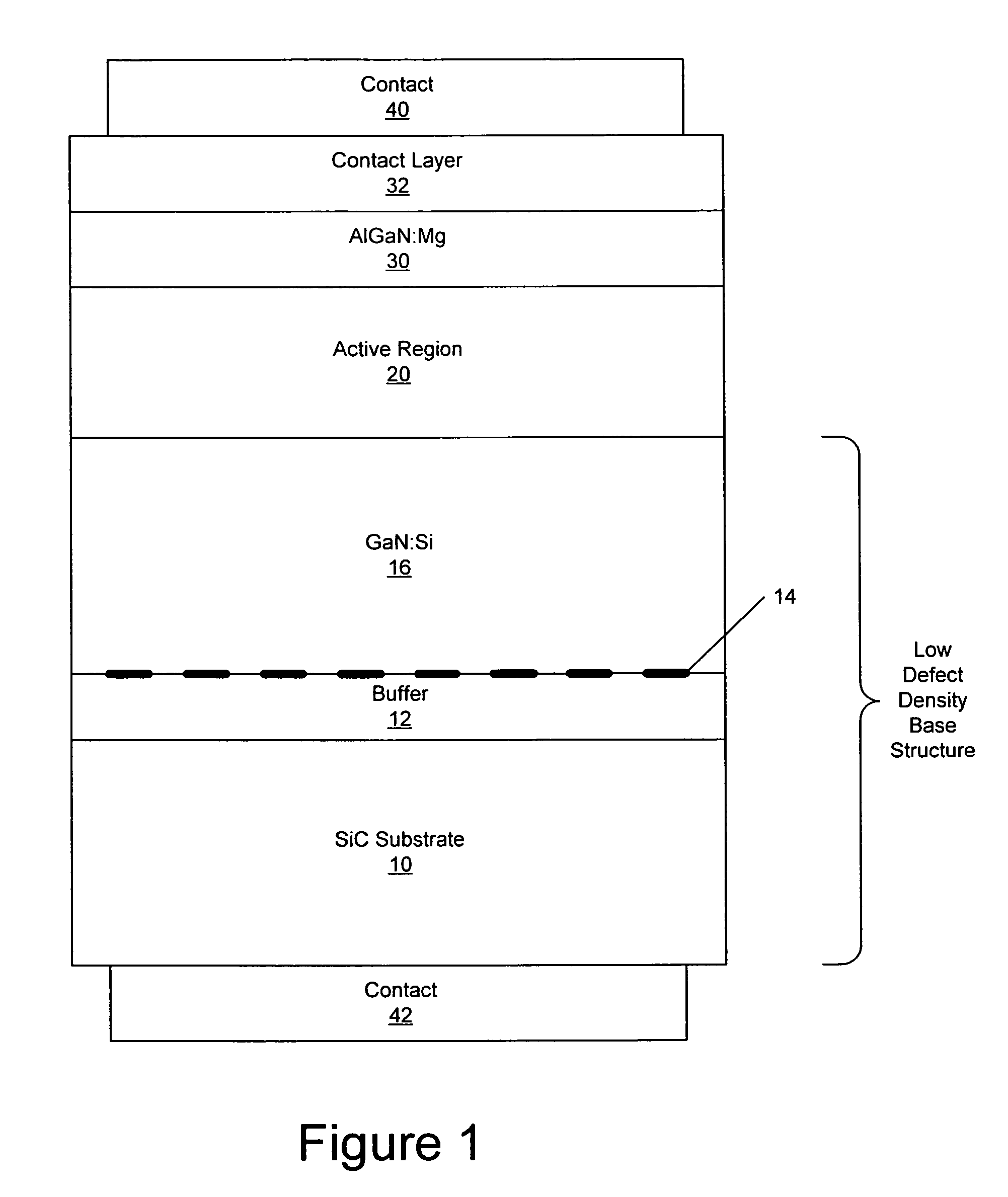
  • Deep ultraviolet light emitting devices and methods of fabricating deep ultraviolet light emitting devices
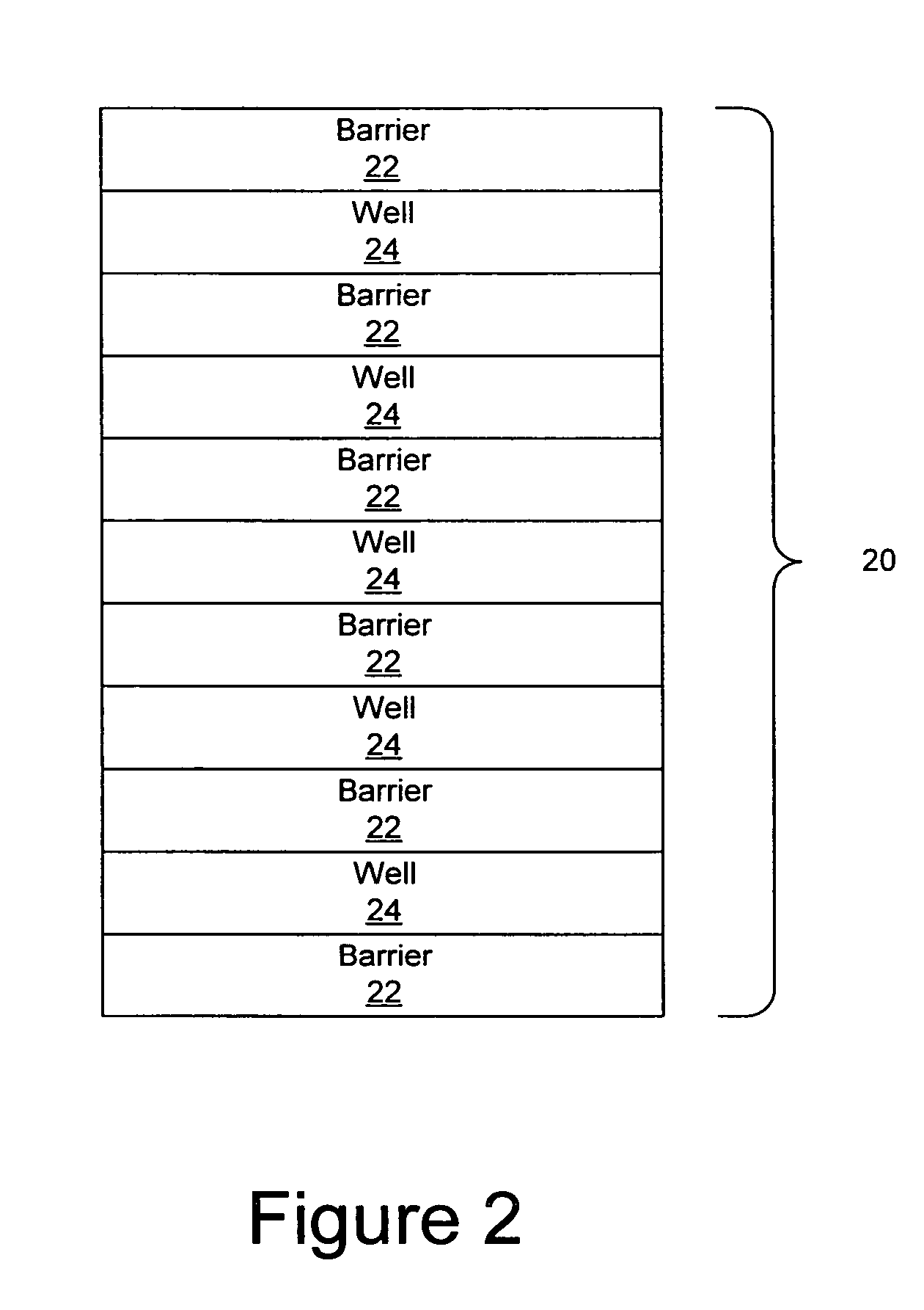
  • Deep ultraviolet light emitting devices and methods of fabricating deep ultraviolet light emitting devices

Examples


Embodiment Construction

[0026] The present invention now will be described more fully hereinafter with reference to the accompanying drawings, in which embodiments of the invention are shown. However, this invention should not be construed as limited to the embodiments set forth herein. Rather, these embodiments are provided so that this disclosure will be thorough and complete, and will fully convey the scope of the invention to those skilled in the art. In the drawings, the thickness of layers and regions are exaggerated for clarity. Like numbers refer to like elements throughout. As used herein the term “and / or” includes any and all combinations of one or more of the associated listed items.

[0027] The terminology used herein is for the purpose of describing particular embodiments only and is not intended to be limiting of the invention. As used herein, the singular forms “a”, “an” and “the” are intended to include the plural forms as well, unless the context clearly indicates otherwise. It will be furt...


PUM


Abstract

Light emitting devices and methods of fabricating light emitting devices that emit at wavelengths less than 360 nm with wall plug efficiencies of at least than 4% are provided. Wall plug efficiencies may be at least 5% or at least 6%. Light emitting devices and methods of fabricating light emitting devices that emit at wavelengths less than 345 nm with wall plug efficiencies of at least than 2% are also provided. Light emitting devices and methods of fabricating light emitting devices that emit at wavelengths less than 330 nm with wall plug efficiencies of at least than 0.4% are provided. Light emitting devices and methods of fabricating light emitting devices having a peak output wavelength of not greater than 360 nm and an output power of at least 5 mW, having a peak output wavelength of 345 nm or less and an output power of at least 3 mW and / or a peak output wavelength of 330 nm or less and an output power of at least 0.3 mW at a current density of less than about 0.35 μA / μm2 are also provided. The semiconductor light emitting devices may have a direct current lifetime of at least 100 hours, at least 500 hours or at least 1000 hours.

Description

FIELD OF THE INVENTION [0001] This invention relates to semiconductor light emitting devices and methods of fabricating light emitting devices. BACKGROUND OF THE INVENTION [0002] Semiconductor light emitting devices, such as Light Emitting Diodes (LEDs) or laser diodes, are widely used for many applications. As is well known to those having skill in the art, a semiconductor light emitting device includes a semiconductor light emitting element having one or more semiconductor layers that are configured to emit coherent and / or incoherent light upon energization thereof. In particular, a light emitting diode or laser diode, generally includes an active region on a microelectronic substrate. The microelectronic substrate may be, for example, gallium arsenide, gallium phosphide, alloys thereof, silicon carbide and / or sapphire. Continued developments in LEDs have resulted in highly efficient and mechanically robust light sources that can cover the visible spectrum and beyond. These attrib...

Claims


Application Information

Patent Timeline
IPC IPC(8): H01L31/00H01L21/00H01L33/06H01L33/12H01L33/32
CPCB82Y20/00H01L33/32H01L33/12H01L33/06
Inventor EMERSON, DAVID TODDBERGMANN, MICHAEL JOHNABARE, AMBERHABERERN, KEVIN
Owner CREE INC
Learn More