Constant voltage power supply circuit and method of controlling the same
a constant-voltage power supply and circuit technology, applied in constant-current supply dc circuits, power conversion systems, instruments, etc., can solve problems such as overshoot voltage and load connected to circuits that fail to work normally
- Summary
- Abstract
- Description
- Claims
- Application Information
AI Technical Summary
Benefits of technology
Problems solved by technology
Method used
Image


Examples
first embodiment
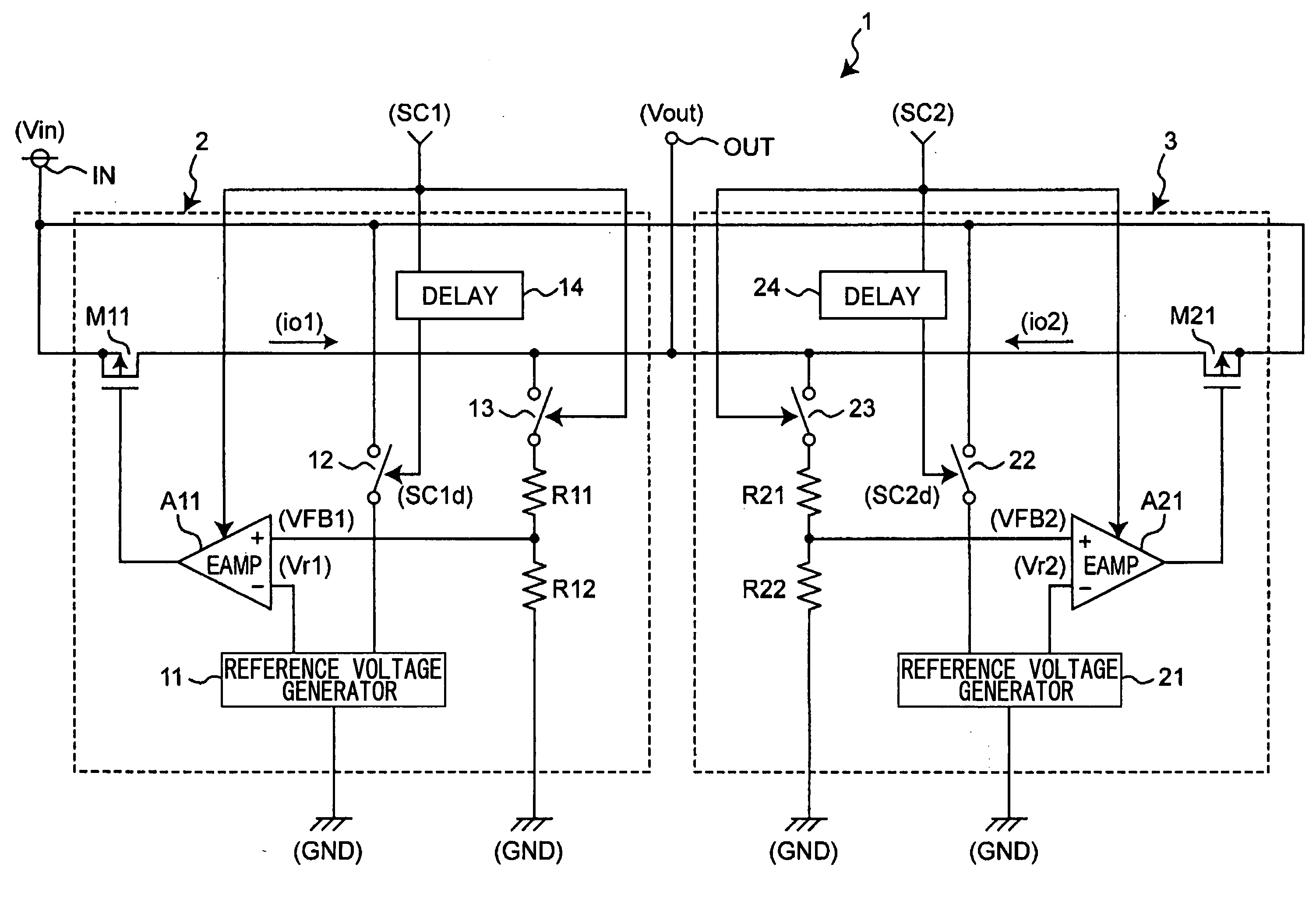
[0128]FIG. 1 is a circuit diagram illustrating an example of a constant-voltage power supply circuit according to a first embodiment of the present invention.
[0129] As shown in FIG. 1, a constant-voltage power supply circuit 1 converts an input voltage Vin input to an input terminal IN to an output voltage Vout output from an output terminal OUT.
[0130] The constant-voltage power supply circuit 1 includes a constant-voltage circuit 2 and a constant-voltage circuit 3, which have the same circuit configuration, and each of the constant-voltage circuits 2 and 3 forms a series regulator.
[0131] The constant-voltage circuit 2 includes a reference voltage generator 11 which generates and outputs a reference voltage Vr1, resistors R11, R12 which divide the output voltage Vout and generate and output a divisional voltage VFB1, an output transistor M11 which is a PMOS transistor that controls a current io1 corresponding to a signal input to a gate of the transistor M11 and outputs the curre...
second embodiment
[0172] In the first embodiment, the rising edge of the reference voltage is delayed by using a delay circuit so as to be later than the rising edge of the divisional voltage. Instead, the operation start timing of the error amplifier may be delayed by a delay circuit. This is described in the present embodiment.
[0173]FIG. 8 is a circuit diagram illustrating an example of the constant-voltage power supply circuit according to a second embodiment of the present invention.
[0174] In FIG. 8, the same reference numbers are assigned to the same elements as described in FIG. 1, and only the differences between FIG. 1 and FIG. 8 are described with overlapping descriptions being omitted.
[0175] The circuit diagram of the constant-voltage power supply circuit shown in FIG. 8 differs from that in FIG. 1 in that the switch 12 is controlled by the control signal SC1, while the switch 22 is controlled by the control signal SC2, the error amplifier A11 is controlled by the delayed control signal ...
PUM
 Abstract
Description
Claims
Application Information
PatSnap Eureka turns technology decisions into work you can execute. Powered by our Innovation Knowledge Graph, it runs expert workflows across engineering, life sciences, materials and intellectual property. Get your review-ready output in minutes.


