Liquid droplet ejection method, head unit, liquid droplet ejection device, electro-optical device, and electronic equipment

Inactive Publication Date: 2006-11-30
SEIKO EPSON CORP
View PDF2 Cites 1 Cited by
  • Summary
  • Abstract
  • Description
  • Claims
  • Application Information

AI Technical Summary

Benefits of technology

[0024] According to the invention, since the electro-optical device of superior quality providing

Problems solved by technology

However, according to the method disclosed in the related art, a different unit is used per kind to eject the plurality of kinds of the functional liquids, so that the total time required for ejecting takes long.
On the other hand, if an attempt is made to eject the plurality of kinds of the functional liqu

Method used


Image

  • Liquid droplet ejection method, head unit, liquid droplet ejection device, electro-optical device, and electronic equipment
  • Liquid droplet ejection method, head unit, liquid droplet ejection device, electro-optical device, and electronic equipment
  • Liquid droplet ejection method, head unit, liquid droplet ejection device, electro-optical device, and electronic equipment

Examples


Embodiment Construction

[0040] Electro-Optical Device

[0041] An embodiment of the invention will be described below with reference to the drawings. To provide each member in a recognizable size, scales in the following drawings are altered as necessary.

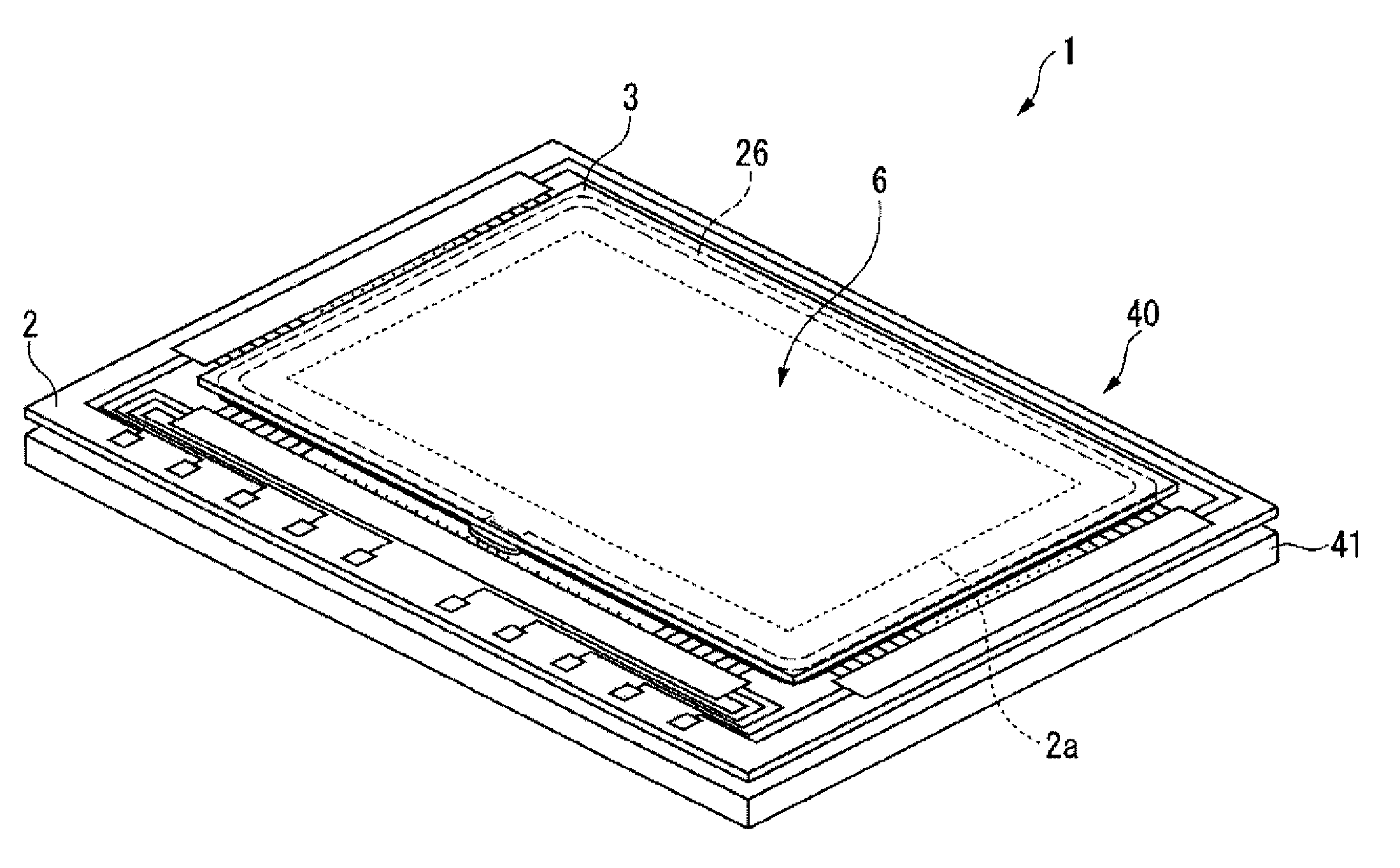
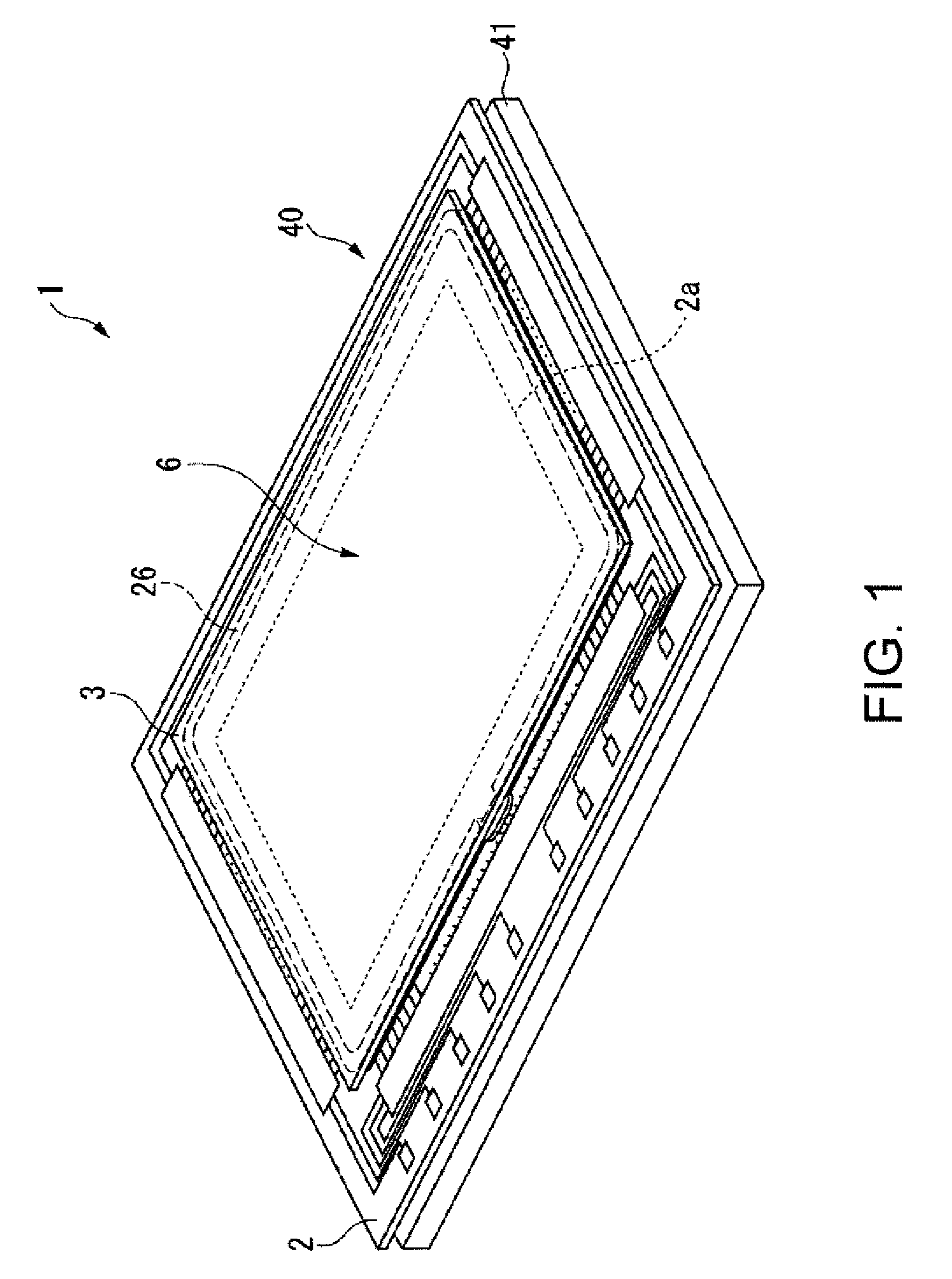
[0042]FIG. 1 is a perspective view showing configuration of a liquid crystal device 1 according to the embodiment.

[0043] As this diagram shows, a liquid crystal device 1 is mainly composed of a liquid crystal panel 40 and a backlight 41. The liquid crystal panel 40 is constructed such that it is made by gluing an active matrix substrate 2 to a color filter substrate 3 through a sealant 26 so as to hold a liquid crystal 6 between the active matrix substrate 2, the color filter substrate 3, and the sealant 26. A display region 2a shown in broken lines in the diagram is a region where images, moving images and the like are displayed.

[0044] The liquid crystal device 1 of the embodiment employs a liquid crystal device of the active matrix type using as a switc...


PUM


Abstract

A liquid droplet ejection method comprises: ejecting a liquid droplet of a functional liquids onto a substrate while scanning relatively the substrate and an ejection head. A plurality of kinds of functional liquids have different drying rates and are ejected onto respective different positions in respective scanning directions during the same scanning operation. Scanning regions of the plurality of kinds of the functional liquids at least partly are overlapped each other.

Description

BACKGROUND OF THE INVENTION [0001] 1. Technical Field [0002] The invention relates to a liquid droplet ejection method, a head unit, a liquid droplet ejection device, an electro-optical device, and electronic equipment [0003] 2. Related Art [0004] A liquid droplet ejection head of an ink-jet printer can eject a minute ink droplet in a dot shape, size of the ink droplet and uniformity of a pitch being highly accurate. This technique is applied to manufacturing fields of a wide variety of products. For example, application is made when forming a color filter of a liquid crystal device, a light-emitting section of an organic EL device, and the like. [0005] Specifically, the liquid droplet ejection head is impregnated with special ink, photosensitive resin liquid (functional liquid) or the like, a droplet of which is ejected to a substrate for an electro-optical device (for example, refer to Japanese Unexamined Patent Publication No. 2004-267927). Since a color filter and a light-emitti...

Claims


Application Information

Patent Timeline
IPC IPC(8): B41J29/38
CPCB41J2/2107B41J2/07B41J2/17B41J29/38B41J29/393
Inventor KATO, TSUYOSHIARUGA, KAZUMI
Owner SEIKO EPSON CORP
Why Eureka
Try Eureka