
Disk drive fly height control based on constant power dissipation in read/write head heaters

a technology of read/write head and height control, which is applied in the direction of magnetic recording, data recording, instruments, etc., can solve the problems of increased wear of both the disk surface and the read-write head, contamination by wear particles, and increased wear of both the slider and the disk surface, so as to improve the accuracy

Active Publication Date: 2006-11-30
TEXAS INSTR INC
View PDF6 Cites 26 Cited by
  • Summary
  • Abstract
  • Description
  • Claims
  • Application Information

AI Technical Summary

Benefits of technology

[0014] It is therefore an object of this invention to provide a disk drive fly height control system and method having improved precision.
[0016] It is a further object of this invention to provide such a system and method in which the power dissipated by a resistive heater in a disk drive read / write head can be precisely controlled regardless of the instantaneous resistance of the resistive heater.
[0019] This invention may be implemented into a fly height controller for a disk drive, in which both the current applied to a read / write head resistive heater and also the voltage across the resistive heater are sensed. A feedback signal corresponding to the product of the sensed voltage and sensed current is produced, and applied to an error amplifier, which in turn modulates the drive signal to the resistive heater. Constant power dissipation through the resistive heater can thus be maintained.

Problems solved by technology

However, low fly heights tend to increase the wear of both the disk surface and the read-write heads.
At extremely low fly heights, relatively small asperities in the disk surface can cause contact between the slider and the disk surface, depleting and degrading lubricants, causing wear on both the slider and the disk surface and causing contamination from wear particles, and in some cases causing the heads to stick at locations of the disk surface where contact is made.
Disk drive manufacturers are thus faced with a tradeoff between disk drive reliability, on one hand, and data density and BER, on the other hand, in determining the desired fly height of the read / write heads.

Method used


Image

  • Disk drive fly height control based on constant power dissipation in read/write head heaters
  • Disk drive fly height control based on constant power dissipation in read/write head heaters
  • Disk drive fly height control based on constant power dissipation in read/write head heaters

Examples


Embodiment Construction

[0025] This invention will be described in connection with its preferred embodiment, namely as implemented into a magnetic disk drive system for an electronic system, such as a computer or a handheld device such as a digital audio player. It is contemplated, however, that this invention may be useful in other applications beyond those illustrated and described in this specification. Accordingly, it is to be understood that the following description is provided by way of example only, and is not intended to limit the true scope of this invention as claimed.

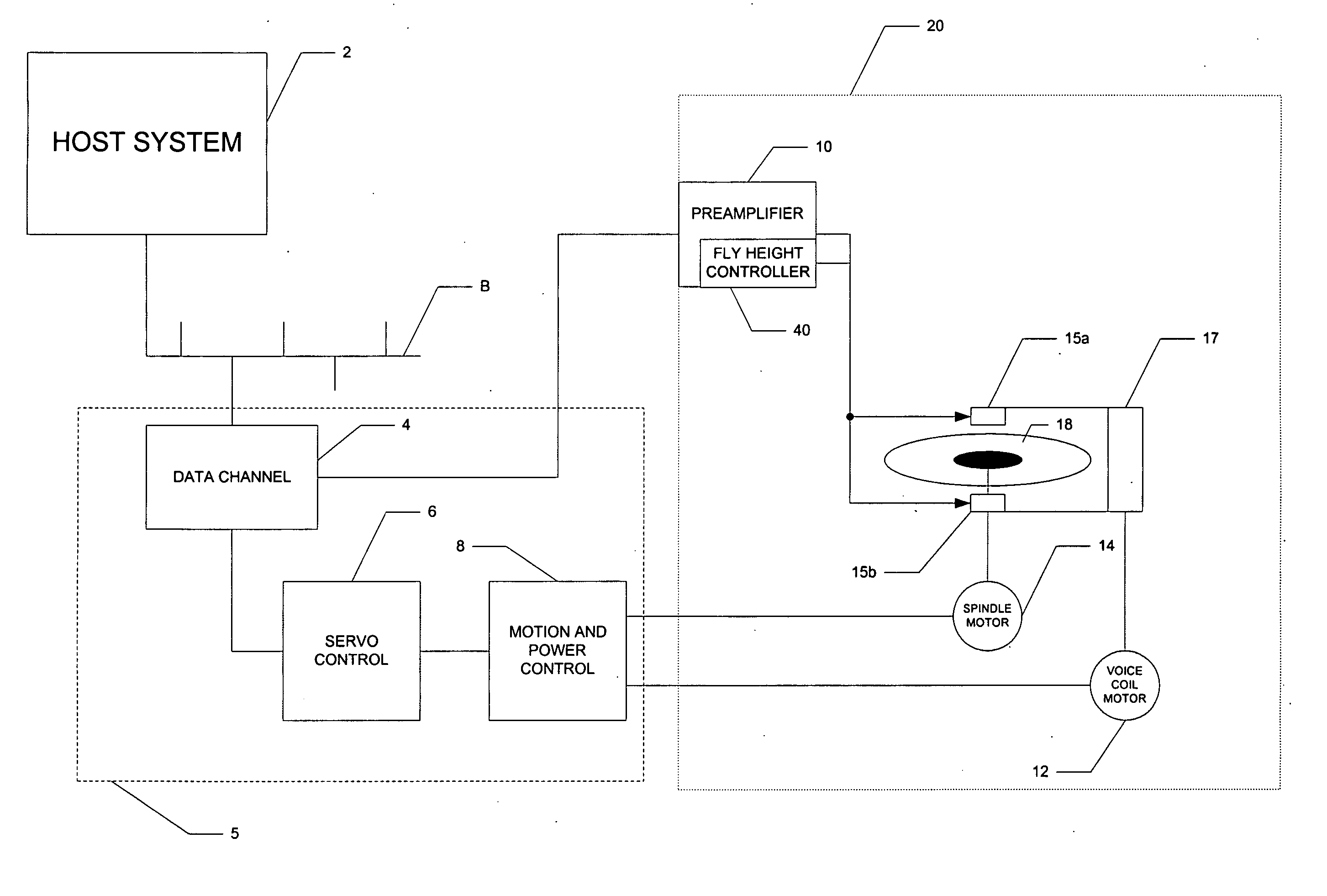
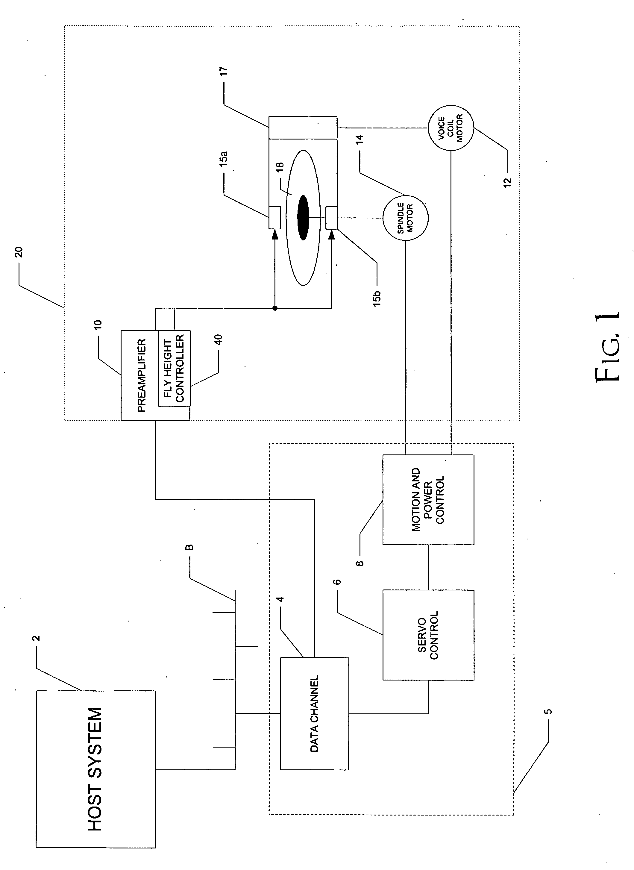
[0026]FIG. 1 illustrates an illustrative example of an electronic system into which the preferred embodiment of the invention is implemented. As mentioned above, a wide variety of modern systems utilize magnetic disk drives, such systems ranging in size from large-scale network services to handheld digital audio players, with personal computers and workstations and other systems between these extremes. In FIG. 1, host system 2 gen...


PUM


Abstract

A fly height controller circuit for a disk drive head having a resistive heater is disclosed. The fly height controller includes an error amplifier that controls a variable current source driving the resistive heater. The error amplifier compares a desired heater power signal with a feedback power signal that is generated by a multiplier. The multiplier receives a signal corresponding to the resistive heater current, for example as generated by a second variable current source also controlled by the error amplifier, and a signal corresponding to a voltage across the resistive heater. A first differential amplifier develops a differential voltage corresponding to the heater voltage. A second differential amplifier is biased by the resistive heater current signal, and receives the differential voltage form the first differential amplifier. A differential current generated by the second differential amplifier produces the feedback power signal as an output voltage.

Description

CROSS-REFERENCE TO RELATED APPLICATIONS [0001] This application claims priority, under 35 U.S.C. §119(e), of Provisional Application No. 60 / 685,918, filed May 31, 2005, which is incorporated herein by this reference.STATEMENT REGARDING FEDERALLY SPONSORED RESEARCH OR DEVELOPMENT [0002] Not applicable. BACKGROUND OF THE INVENTION [0003] This invention is in the field of control circuitry for magnetic storage media drives, and is more specifically directed to fly height control circuitry involving read / write head heaters in such drives. [0004] Continuing progress toward higher performance yet less expensive electronic systems has resulted in large part from advances in nonvolatile data storage technology. The “workhorse” technology for nonvolatile data storage has, of course, been the magnetic disk drive. Magnetic disk drives are used over a wide range of electronic systems, including large-scale network servers, desktop workstations, portable computers, and even now in modern handhel...

Claims


Application Information

Patent Timeline
IPC IPC(8): G11B21/02
CPCG11B5/6064G11B5/60
Inventor BRANNON, CRAIG M.RANMUTHU, INDUMINI W.TAN, SIANG TONG
Owner TEXAS INSTR INC
Learn More