
High-power LED lamp having heat dissipation assembly

a technology of heat dissipation assembly and led lamps, which is applied in the direction of printed circuit aspects, semiconductor devices of light sources, light and heating apparatus, etc., can solve the problems of compromising the reliability and safety of the lamps, excessive heat continuously accumulating, and high-power and high-bright lamps still suffer the traditional problem of heat dissipation, etc., to achieve fast and evenly conducted and extracted, improve performance, and improve the effect of performan

Inactive Publication Date: 2006-11-30
LIN KUANG TSENG
View PDF2 Cites 9 Cited by
  • Summary
  • Abstract
  • Description
  • Claims
  • Application Information

AI Technical Summary

Benefits of technology

[0008] The primary purpose of the present invention is to provide a LED lamp with a heat dissipation assembly such that, if the LED lamp is operated in an air-tight space and under a rigorous condition, the LED lamp is protected from the excessive heat accumulated in the air-tight space. The present invention of course could be applied to LED lamps operated in an open environment with an even better performance, as the air convection already provides some degree of heat dissipation.
[0009] The present invention utilizes a heat conducting plastic pad attached to a heat dissipation plate, both having a large planar surface area. The heat generated by LED a lamp made of a large number of gathered LEDs is quickly and evenly conducted and extracted by the heat conducting plate, and then dissipated evenly and quickly via the large surface area of the heat dissipation plate, so the lamp could be cooled down effectively and the LEDs, even though housed in an air-tight space and operated for an extended period time under a high power, could be protected from the excessive heat.

Problems solved by technology

Despite the progress of the lamps, high-power and high brightness lamps still suffer the traditional problem of heat dissipation.
As these lamps, especially road lamps and projecting lamps, are often operated in an air-tight space and under a rigorous condition, excessive heat is continuously accumulated in the air-tight space, and the reliability and safety of the lamps are thereby compromised.
However, these LED lamps are not immune from the heat dissipation problem of conventional lamps and, due to their characteristics, LED lamps are easily damaged from the excessive heat.

Method used


Image

  • High-power LED lamp having heat dissipation assembly
  • High-power LED lamp having heat dissipation assembly
  • High-power LED lamp having heat dissipation assembly

Examples


Embodiment Construction

[0016] The following descriptions are of exemplary embodiments only, and are not intended to limit the scope, applicability or configuration of the invention in any way. Rather, the following description provides a convenient illustration for implementing exemplary embodiments of the invention. Various changes to the described embodiments may be made in the function and arrangement of the elements described without departing from the scope of the invention as set forth in the appended claims.

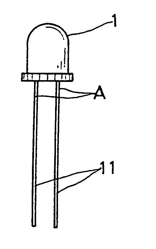
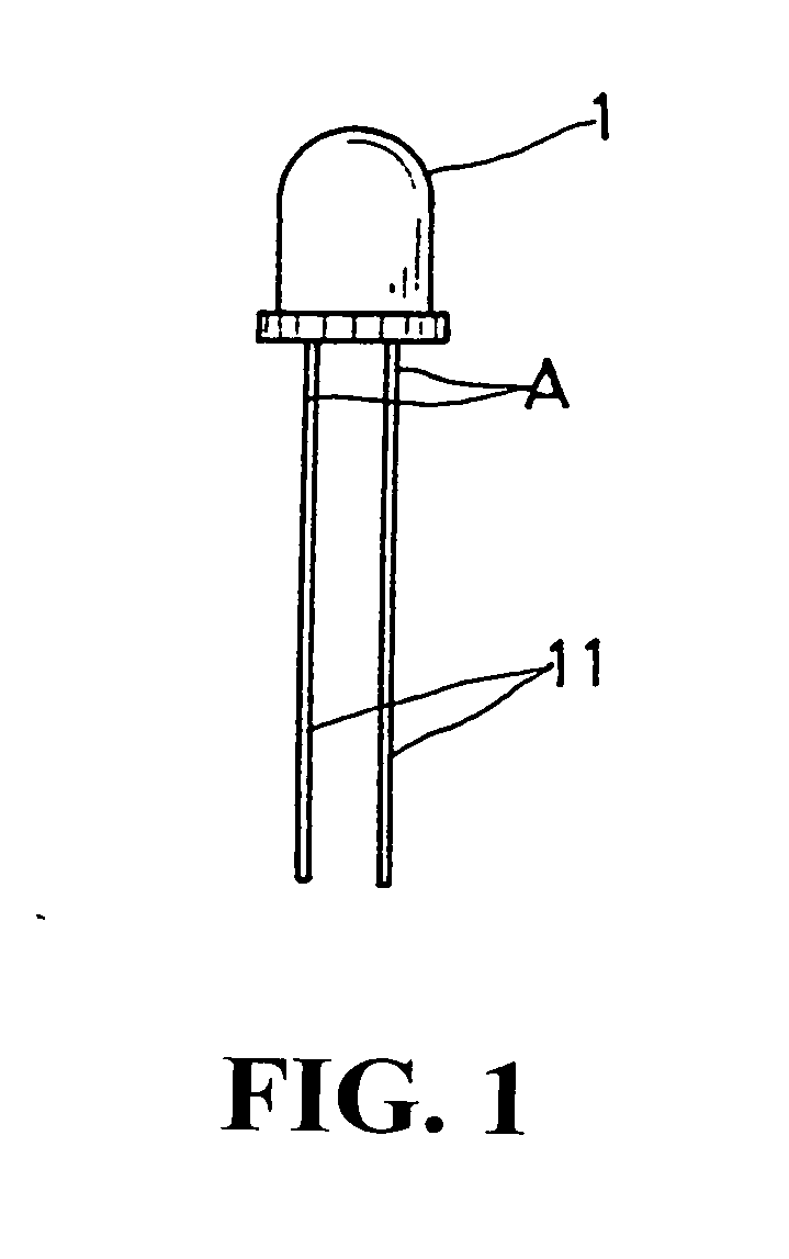
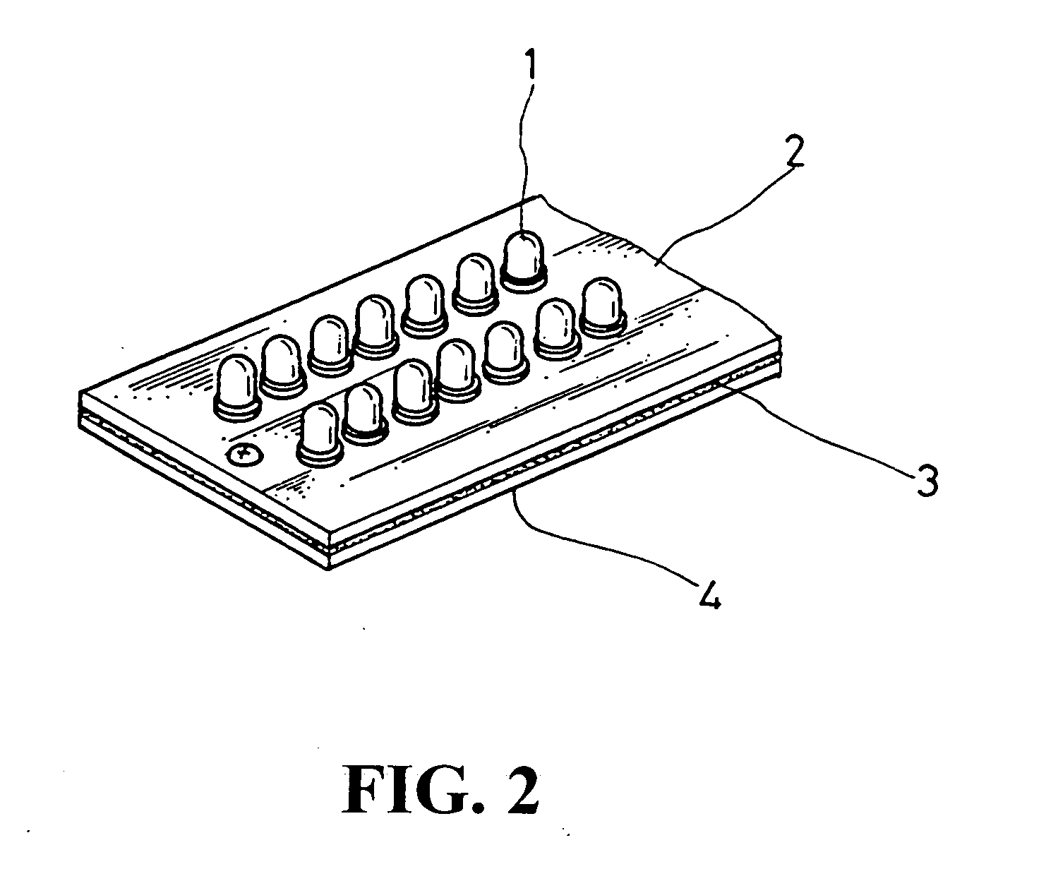
[0017] As illustrated in FIG. 3, the present invention mainly contains a plurality of LEDs 1, a heat dissipation plate 2, a heat conducting pad 3, and a base plate 4.

[0018] The LEDs 1 are of a high brightness type, and the LEDs 1 are gathered and positioned uniformly on a side of the heat dissipation plate 2 so as to form a planar and projecting light source. The heat conducting pad 3 is interposed between the heat dissipation plate 2 and the base plate 4. Each of the LEDs 1 is installed by ha...


PUM


Abstract

A high-power LED lamp having a heat dissipation assembly is provided. The heat generated by a lamp made of a large number of gathered LEDs is quickly and evenly conducted and dissipated, so the lamp could be cooled down effectively and the LEDs, even though housed in an air-tight space and operated for an extended period time under a high power, could be protected from the excessive heat.

Description

BACKGROUND OF THE INVENTION [0001] (a) Technical Field of the Invention [0002] The present invention generally relates to LED lamps, and more specifically to a high-power lamp having a heat dissipation assembly. [0003] (b) Description of the Prior Art [0004] For the past several decades, lamps have evolved from the incandescent light bulbs to fluorescent light tubes on to the currently popular energy-saving light tubes (such as the PL lamps) or bulbs (such as light bulbs with ballast). Despite the progress of the lamps, high-power and high brightness lamps still suffer the traditional problem of heat dissipation. As these lamps, especially road lamps and projecting lamps, are often operated in an air-tight space and under a rigorous condition, excessive heat is continuously accumulated in the air-tight space, and the reliability and safety of the lamps are thereby compromised. [0005] Recently light emitting diodes (LEDs) have been applied in these high-power road lamps or projecting...

Claims


Application Information

Patent Timeline
Patent Type & Authority Applications(United States)
IPC IPC(8): F21V29/00
CPCF21K9/00H05K1/0203H05K3/3447F21V29/89H05K2201/10553F21V29/20F21V29/87H05K2201/10106
Inventor LIN, KUANG-TSENG
Owner LIN KUANG TSENG
Learn More