[0013] This roll paper transportation device can hold the paper detection unit together with the buffer mechanism unit in a housing unit formed by the buffer mechanism unit in common with the paper detection unit. More particularly, by locating all of the paper detection unit within the area occupied by the buffer mechanism unit, the space required to render both can be significantly reduced compared with arrangements in which the buffer mechanism unit and paper detection unit are located in different places. The paper detection unit and buffer unit can also function independently without interfering with the operation of the other. The roll paper transportation device can thus be rendered more compactly while achieving the functions of the paper detection unit and roll paper transportation device.
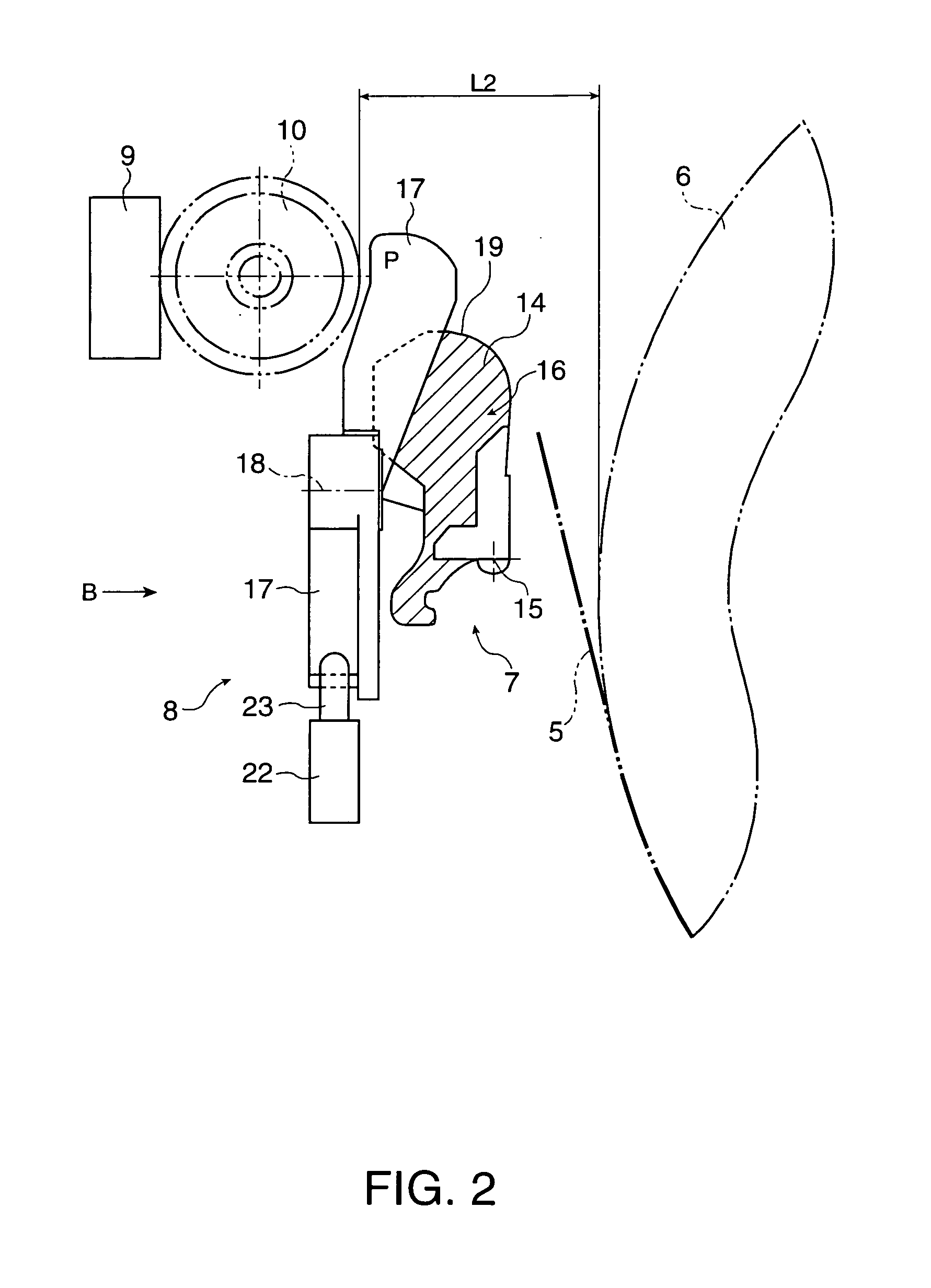
[0015] The buffer plate of the buffer mechanism unit in this aspect of the invention provides a guide surface for guiding the roll paper. The guide surface of the buffer plate is disposed to a position that changes the transportation direction of the roll paper, guides the roll paper along the guide surface, and compensates for movement of the roll paper side to side and vertically. By thus guiding the roll paper over this guide surface the roll paper can be conveyed correctly along the transportation direction. The buffer plate is also arranged so that the buffer plate can roll for causing the roll paper transportation path to shift from one position to another respectively. When the roll paper is pulled suddenly off the paper roll such as at the start of printing, the tension on the roll paper momentarily increases greatly. The resulting
high tension (or change in tension) can interfere with or prevent normal paper transportation, and can result in uneven stretching of the roll paper, wrinkles, and even
tears. The resulting overload on the paper feed motor can also prevent the motor from operating normally or even damage the motor. To avoid such problems, the buffer plate rolls in the direction alleviating this tension when high tension is suddenly applied to the roll paper i.e. pivots in the direction to shorten the length of the transportation path. This rolling prevents applying excessive tension to the roll paper.
[0017] The paper detection unit in this aspect of the invention has a detection lever disposed so that when roll paper is loaded and contacts the detection lever, the detection lever is depressed by the roll paper and the paper detection unit operates, thereby detecting if roll paper is loaded or not. When tension is applied to the roll paper and the buffer plate pivots, the detection lever pivots in conjunction with the buffer plate and is held in a position not protruding from the guide surface of the buffer plate. If the detection lever does not move in conjunction with the guide surface and protrudes from the guide surface, the roll paper will rub against the end of the detection lever, leaving striped lines or marks in the paper, and resulting in printing defects in the printed roll paper. If
thermal paper is used, this friction can cause the paper to discolor and become unusable. By causing the detection lever to move in conjunction with the guide surface and not protrude from the guide surface, the quality of the printed roll paper is not impaired.
[0022] More specifically, when the switch lever is pushed by the curved surface of the
cam, the switch lever inside the mechanical switch swings and contacts a contact terminal, thereby operating the mechanical switch. Furthermore, because the mechanical switch is operated by means of a detection lever,
cam, and switch lever, the small force exerted on the switch lever by the roll paper can be amplified by adjusting the lengths of the levers and the shape of the
cam, and the mechanical switch can be reliably operated. Using a detection lever and cam also enables increasing the distance from the roll paper to the mechanical switch, and discharging static produced by the roll paper to the mechanical switch can be reliably prevented.
[0024] When the roll paper is loaded in this aspect of the invention, the switch lever follows the cam and rides onto and in contact with the curved surface of the cam. The switch lever rides on the curved surface of the cam, contacts the contact terminal of the mechanical switch, and operates the mechanical switch. As the load changes while conveying the roll paper and the detection lever moves repeatedly in conjunction with this change in the load, the switch lever slides along the curved surface of the cam but does not rock because the curved cam surface is concentric with the rotary axis of the detection lever. More particularly, the switch lever does not pivot repeatedly as the position of the roll paper changes slightly, and the switch lever therefore does not slide against the contact terminal of the mechanical switch. Sliding between the switch lever and the contact terminal of the mechanical switch can thus be limited, and contact wear caused by such sliding and poor electrical contact caused by contact wear can be prevented.
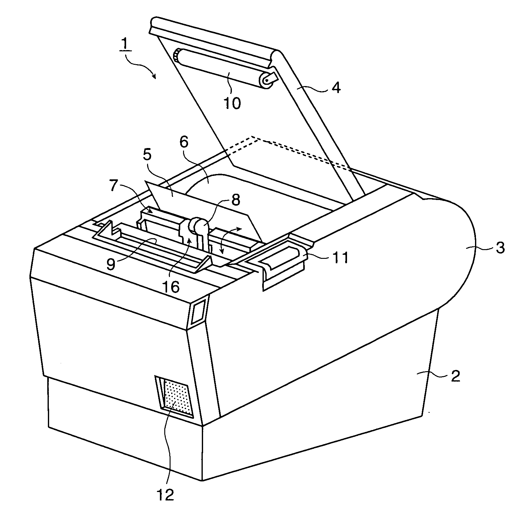
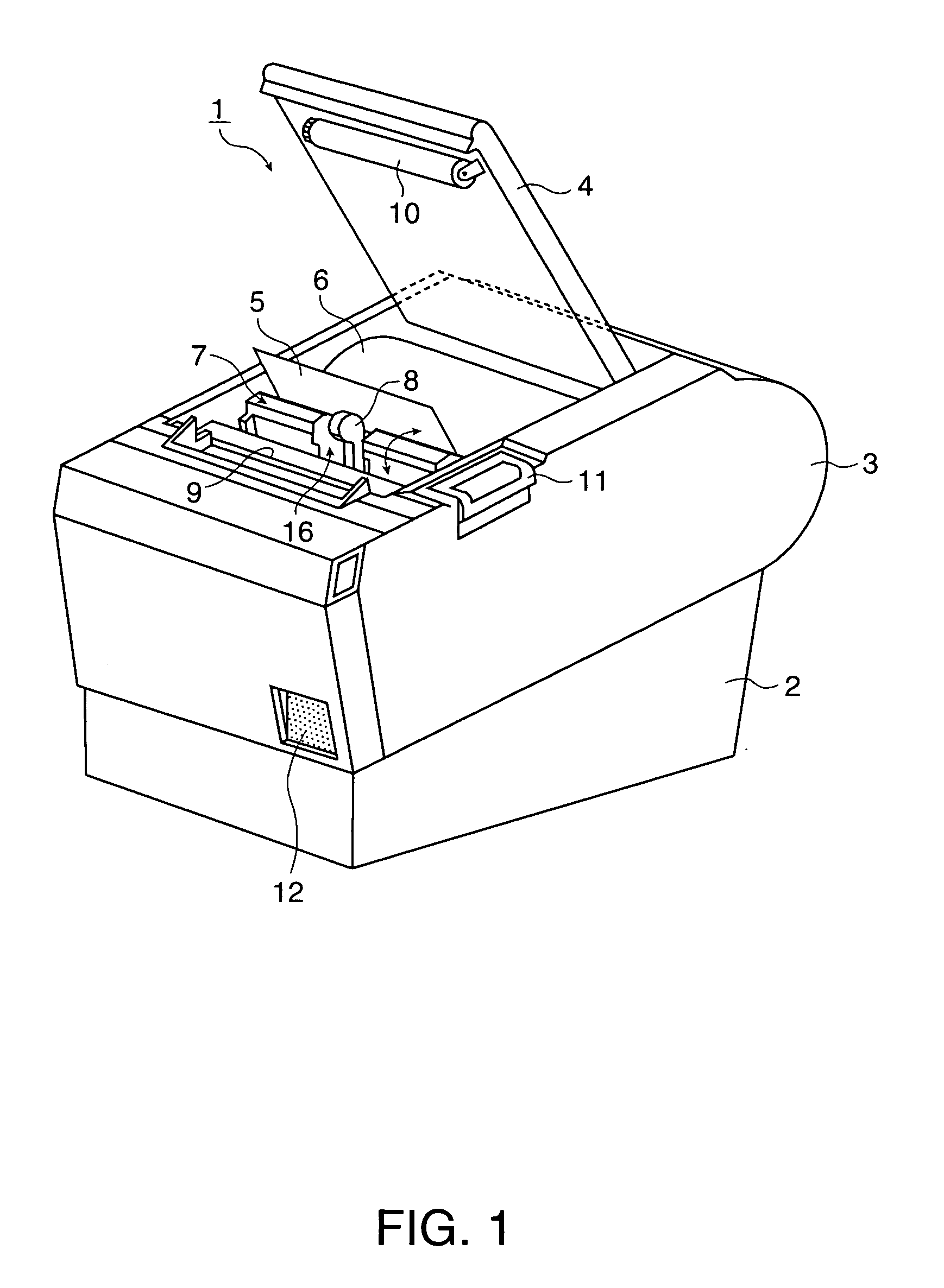
[0026] This printing apparatus comprises a compact roll paper transportation device including a paper detection unit and a buffer mechanism unit forming a housing unit for housing the paper detection unit with each at least partially occupying
common space provided in the buffer mechanism unit for operating in
unison either independent of one another or in conjunction with one another. As a result, the printing apparatus can alleviate producing excessive tension on the roll paper by means of the rocking mechanism of the buffer plate of the buffer mechanism unit. Furthermore, because the detection lever that detects the roll paper does not protrude from the guide surface of the buffer plate, damage caused by the detection lever
rubbing against the roll paper can be prevented. Furthermore, when a mechanical switch is used in the paper detection unit, sliding between the switch lever and the contact terminal of the mechanical switch can be limited, and contact wear caused by such sliding and poor electrical contact caused by contact wear can be prevented. Discharging
static electricity produced by the roll paper can also be prevented, thus also preventing damage to the paper detection unit. A compact printing apparatus affording the benefits described above can thus be provided by rendering the roll paper transportation device of this invention in the printing apparatus.

