Twist drill

Inactive Publication Date: 2006-11-30
NACHI-FUJIKOSHI
View PDF4 Cites 42 Cited by
  • Summary
  • Abstract
  • Description
  • Claims
  • Application Information

AI Technical Summary

Benefits of technology

[0008] An object of the invention is to provide a twist drill having cutting edges that minimize wear and chipping of corner portions and damage to leading edges in a drilling operation using no cutting oil, or a drilling operation with spraying of a very small amount of cutting oil to the drill, or

Problems solved by technology

When a drilling operation is carried out by using the twist drill of FIG. 3 without using cutting oil or with spraying of a very small amount of cutting oil to the drill, insufficient strength of the leading edge causes problems of rapid progression of wear of corner portions and breakage of the leading edge.
Howev

Method used


Image

  • Twist drill
  • Twist drill
  • Twist drill

Examples


example 1

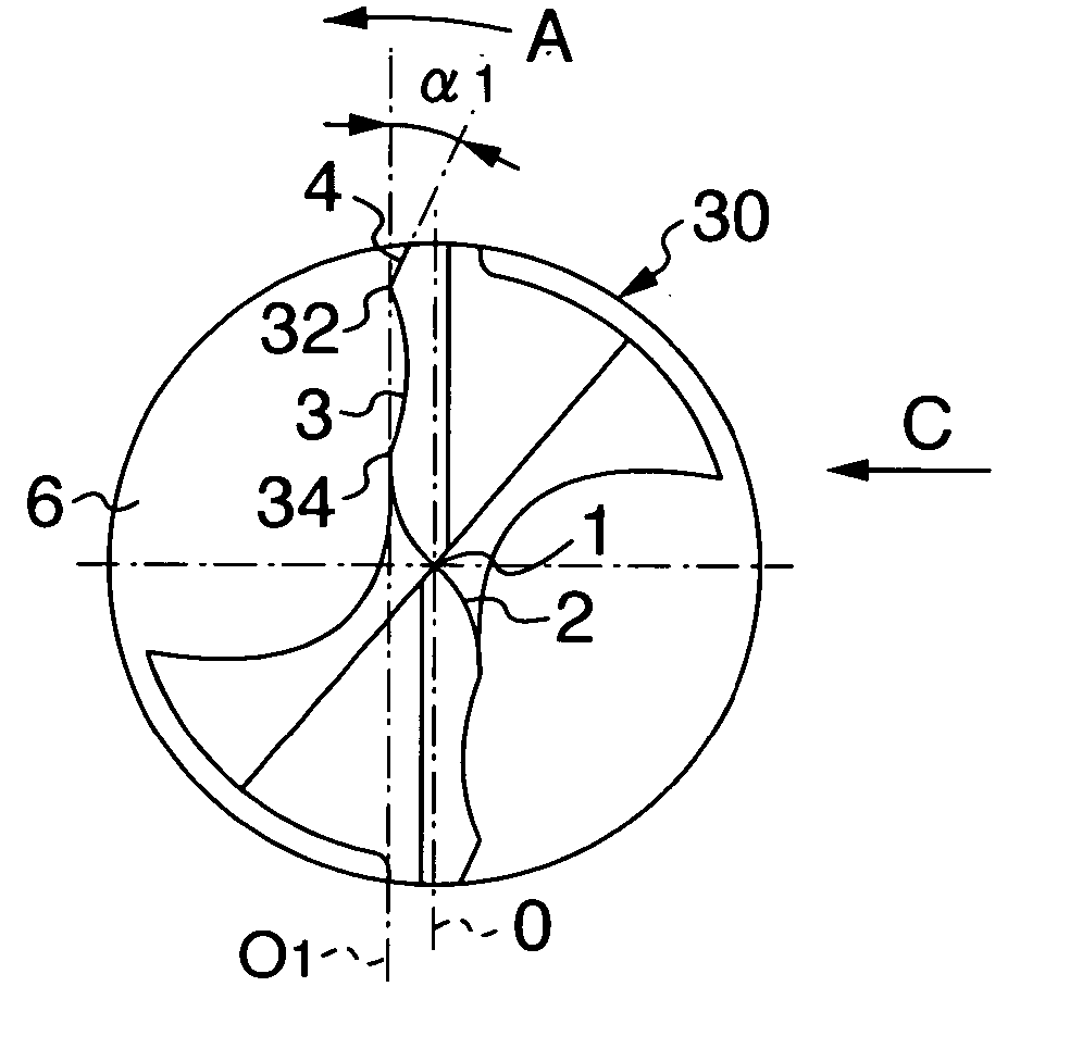
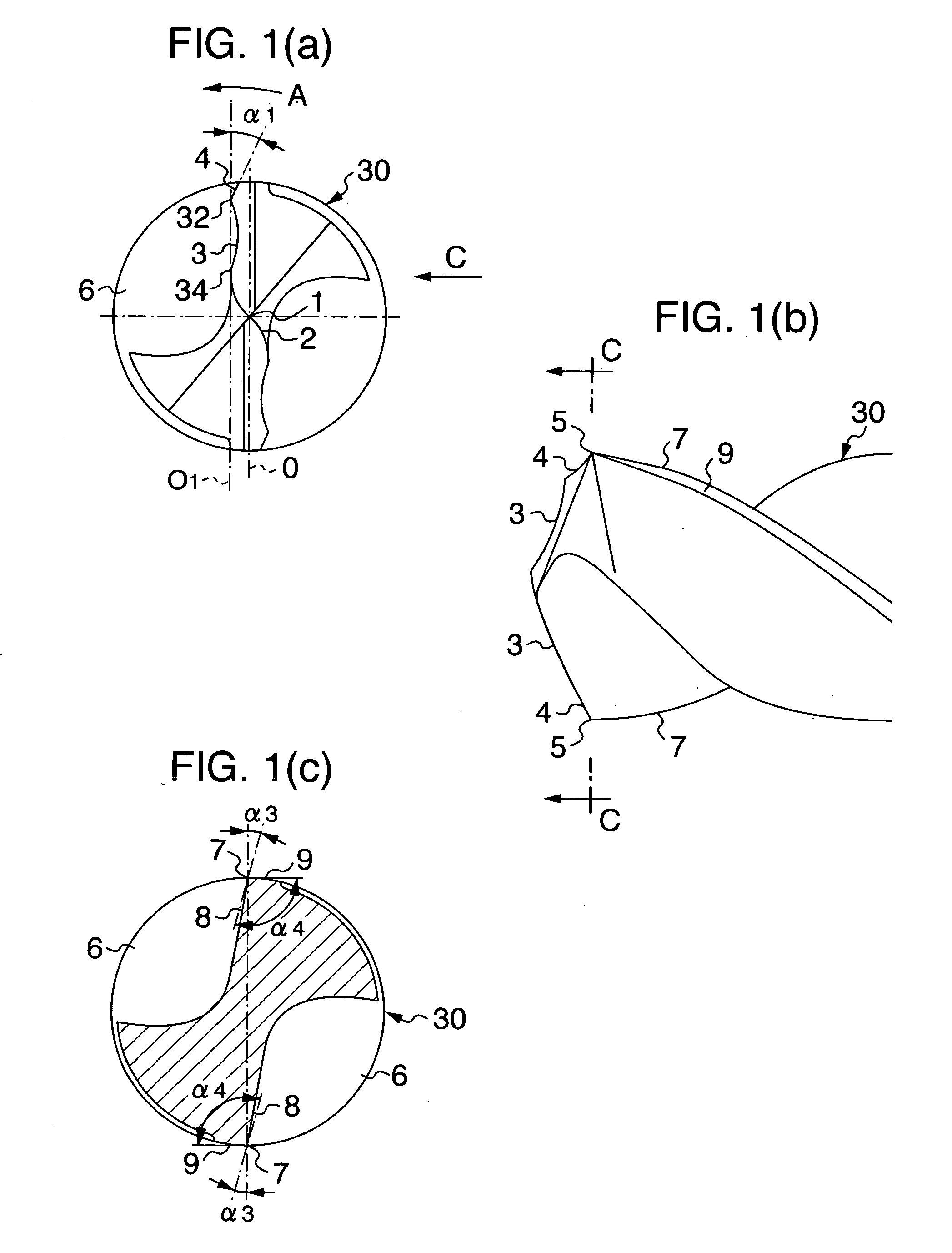
[0028] As the drill of the invention having the main cutting edges 3 of the centrally-concaved shape, a twist drill of cemented carbide configured as shown in FIG. 1 was manufactured. This twist drill has an outer diameter of 6 mm, a total length of 72 mm, a flute length of 28 mm, a point angle of 140°, and a margin width of 0.4 mm. A radius of curvature of the concave-shaped main cutting edges is 30% of the drill diameter (1.8 mm in radius), with their connection portions with the corner cutting edges slightly rounded convex. A radial length of the corner cutting edges is 7% of the drill diameter (0.42 mm in length) and an angle α1, which the corner cutting edges make with respect to a straight line (O1) parallel to a plane passing through the axis, is set to 10°.

[0029] For comparison, a twist drill of cemented carbide as shown in FIG. 3 was manufactured which had an outer diameter of linear main cutting edges 103 of 6 mm, a total length of 72 mm, a flute length of 28 mm, a point ...

example 2

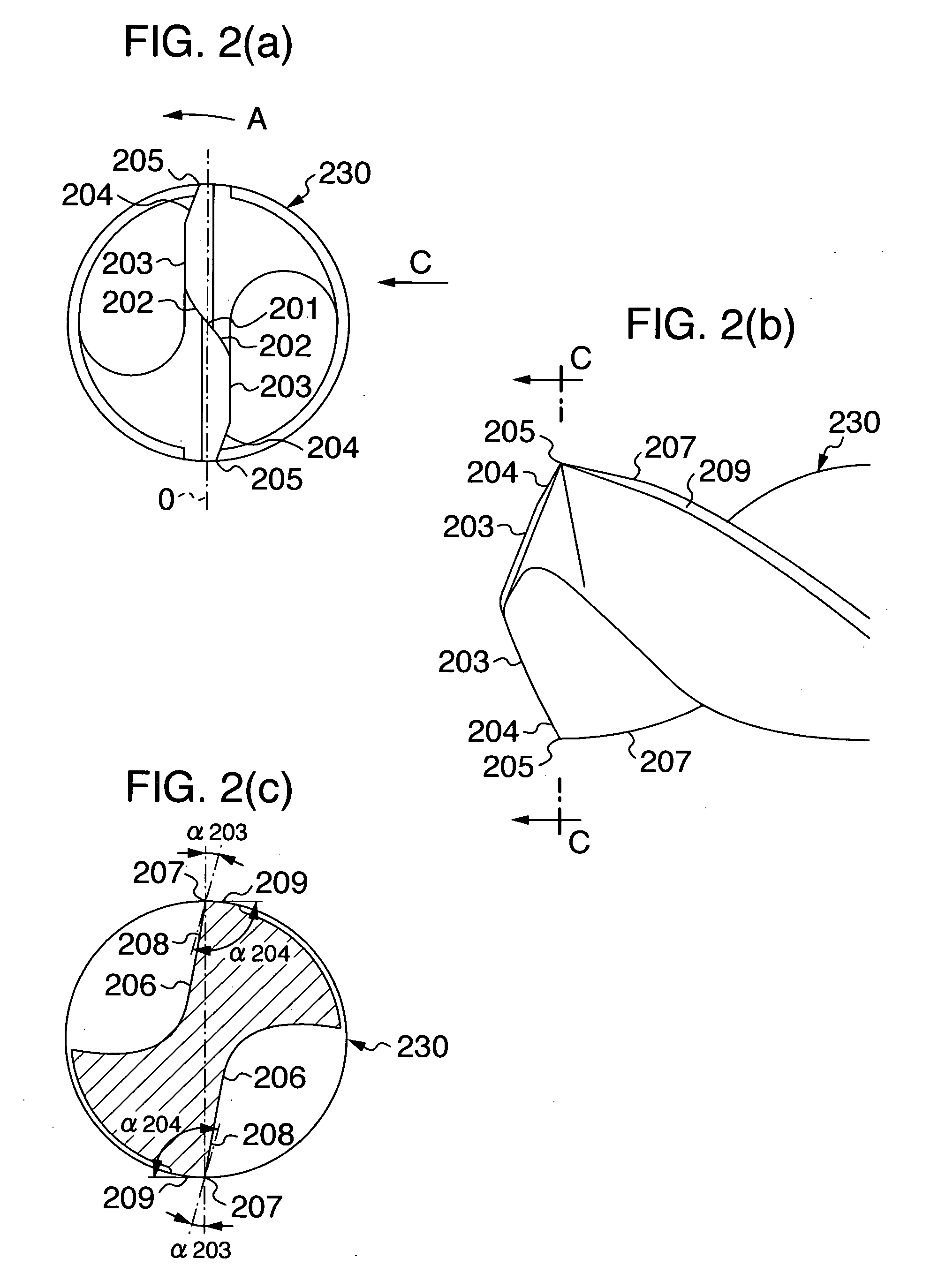
[0032]FIG. 5 shows the result of a drilling test conducted as a wet cutting performance test, similarly to the example 1, with use of the drill of the invention, the conventional drill having the linear main cutting edges 103 shown in FIG. 3 and the conventional drill having the receding corner cutting edges 204 shown in FIG. 2. In these wet cutting performance tests, a work piece S50C (200HB) was drilled at a cutting speed of 80 m / min and a feed speed of 640 mm / min to a hole depth of 17 mm with use of a water-soluble cutting fluid, and the shapes of chips produced and the number of holes drilled up to the ends of service life of the drills were investigated. An upper part of the figure shows the shapes of chips and a lower part shows the number of holes drilled until the ends of service life.

[0033] As for the conventional twist drill with the linear cutting edges, the chips formed were somewhat elongated and the number of holes drilled was small because of the progression of corne...


PUM

PropertyMeasurementUnit
Fractionaaaaaaaaaa
Fractionaaaaaaaaaa
Thicknessaaaaaaaaaa

Abstract

A twist drill has a pair of concave-shaped main cutting edges continuous outwardly to respective center cutting edges, and a pair of corner cutting edges receding at an angle from the outer ends of the respective main cutting edges with respect to a drill rotation direction. Respective ends of the concave-shaped main cutting edges are situated on a straight line almost parallel to a plane passing through a drill axis. These cutting edges have a function of minimizing wear and chipping of corner portions and damage to leading edges in a drilling operation using no cutting oil, or a drilling operation wherein a very small amount of cutting oil is sprayed to the drill, or in a drilling operation on relatively hard steel. They also have a function of facilitating breaking of cut chips into pieces during a drilling operation using cutting oil and during a drilling operation on steel of relatively low hardness such as general structural rolled steels and low carbon steels.

Description

BACKGROUND OF THE INVENTION [0001] The present invention relates to a twist drill that is capable of a drilling operation without using cutting oil or a drilling operation with spraying of a very small amount of cutting oil to the drill and which may need no oil hole. This twist drill has a shape of cutting edges that, during a drilling operation, minimizes wear of corner portions and breaks chips of material being formed into small pieces. [0002] One example of a conventional twist drill, which can perform a drilling operation without using cutting oil or a drilling operation with spraying of a very small amount of cutting oil to the drill and which may require no oil hole, is shown in FIG. 3. FIG. 3(a) is a plan view of a tip portion of the twist drill, FIG. 3(b) is a side view as viewed in a direction C of FIG. 3(a), and FIG. 3(c) is a cross-sectional view taken along the line C-C passing through points 105, 105 in FIG. 3(b) perpendicularly to a drill axis. [0003] Cutting edges o...

Claims


Application Information

Patent Timeline
IPC IPC(8): B23B51/00
CPCB23B51/02B23B2251/04Y10T408/9097B23B2251/18B23B2251/14
Inventor GOSHIMA, YASUSHI
Owner NACHI-FUJIKOSHI
Why Eureka
Try Eureka