Radio receiver and reserved band filter

a radio receiver and reserved band technology, applied in the direction of electrical equipment, transmission, etc., can solve the problems of high cost of high power fm radio transmission, many low power fm radio stations using reserved bands are often overpowered by commercial stations, and have reception problems, so as to improve the reception of radio signals, and improve the effect of radio signal reception

Inactive Publication Date: 2006-11-30
KENWOOD CO LTD
View PDF9 Cites 7 Cited by
  • Summary
  • Abstract
  • Description
  • Claims
  • Application Information

AI Technical Summary

Benefits of technology

[0018] An object of the present invention is to provide a filter, a filter circuit or a receiver for improved reception of a radio signal where the filter operates before an intermediate frequency stage of the radio receiver or before intermediate frequency downconversion or between an input and an intermediate frequency stage input.
[0019] Another object of the present invention is to provide a filter, a filter circuit or a receiver for improved reception of a radio signal where a first radio frequency range passed by a first filter is directly adjacent to or at least partially overlaps with a second radio frequency range passed by a second filter.
[0020] A further object of the present invention is to provide a filter, a filter circuit or a receiver for improved reception of a radio signal with a tuner selectively electrically or operatively connected to first and second band pass filters and which operates such that the first band pass filter selectively electrically connects between an input and a mixer when the tuner is tuned to a first radio frequency range, and such that the second band pass filter selectively electrically connects between the input and the mixer when the tuner is tuned to a second radio frequency range.
[0021] Still another object of the present invention is to provide a filter, a filter circuit or a receiver for improved reception of a radio signal where a control circuit comprises a switch electrically connected between an RF signal source and each of an input of a first radio frequency or band pass filter and an input of a second radio frequency filter.
[0022] An even further object of the present invention is to provide a filter, a filter circuit or a receiver for improved reception of a radio signal where a control circuit comprises a switch electrically connected between an RF signal source and an input of a first radio frequency or band pass filter, and where a second radio frequency or band pass filter is electrically connected between the RF signal source and the control circuit.
[0023] Yet another object of the present invention is to provide a filter, a filter circuit or a receiver for improved reception of a radio signal where an RF signal source is an antenna.

Problems solved by technology

Due to the comparatively high cost of high power FM radio transmission, many public radio stations in the U.S. are comparatively low power stations, that is less than 20 KW effective radiated power (ERP), or even less than 1 KW ERP.
As specifically noted by the FCC, LPFM stations are not protected from interference that may be received from other classes of FM stations.
As a result of high power commercial FM radio stations operating in the same metropolitan area, many low power FM radio stations using the reserved band are often overpowered by the commercial stations and have reception issues.
A problem occurs in the reception of signals from lower power FM radio stations using prior art radio receivers such as the radio receiver 10 described above.
Specifically, when prior art FM radio receivers are tuned to a frequency in the reserved band, the radio receiver may be desensitized by a signal from a high power commercial FM radio station and unable to receive a signal from a lower power noncommercial FM radio station, or the front end of the receiver can be saturated by the high power commercial FM radio station.
Although it is possible to improve the performance of a radio receiver by filtering out each undesired station, it is not practical or economical.
There are 101 possible FM station frequency allocations in the U.S. FM band, and it is not feasible to provide a filter for each station in the radio receiver.

Method used


Image

  • Radio receiver and reserved band filter
  • Radio receiver and reserved band filter
  • Radio receiver and reserved band filter

Examples


Embodiment Construction

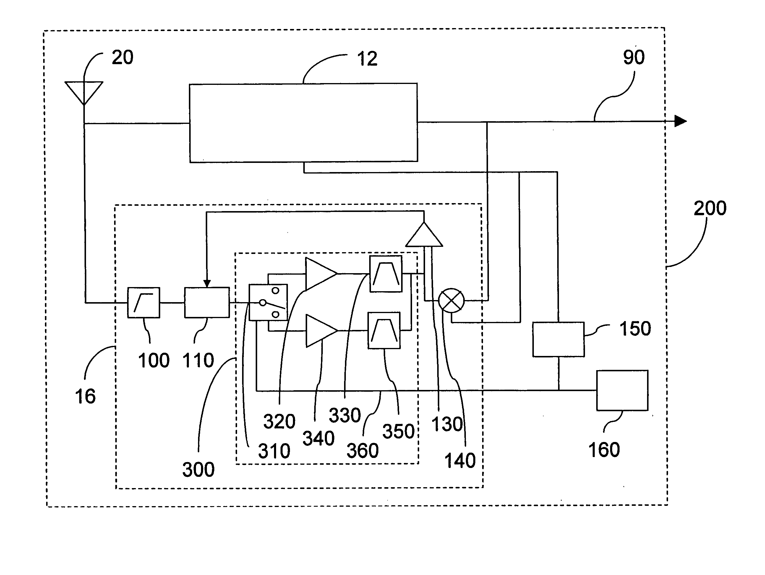
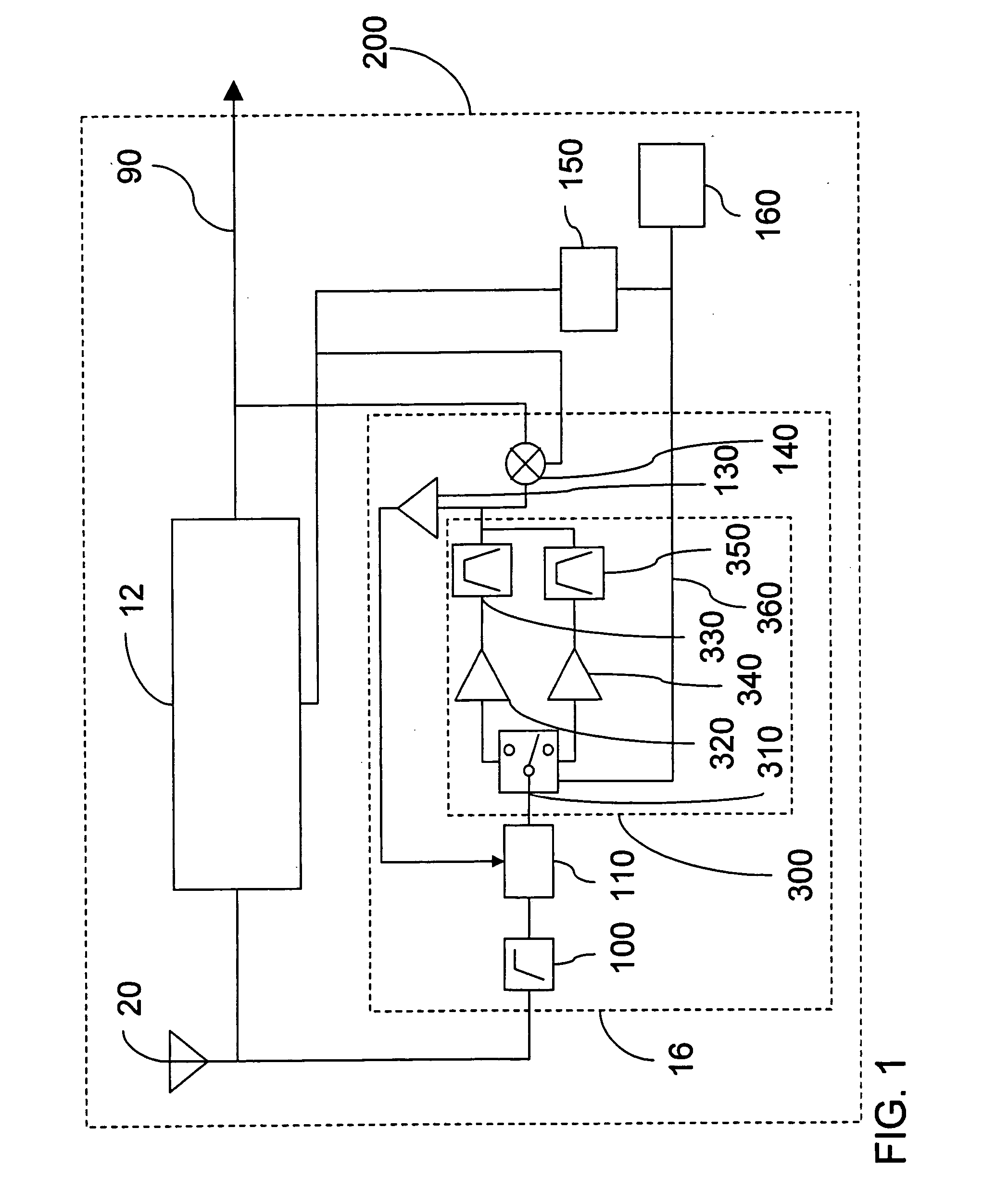
[0029]FIG. 1 shows one embodiment of the present invention, particularly adapted for operation in the U.S. Specifically, FIG. 1 shows a block diagram of a front end of an AM / FM radio RF receiver 200. The front end of the radio receiver 200 may comprise a signal input 20 connected to an AM receiver circuit 12 and an FM receiver circuit 16. The FM receiver circuit 16 may comprise the following features: an FM band high pass filter 100 connected to the signal input 20, an FM PIN diode detector 110 connected to the FM band high pass filter 100, a filter circuit 300 connected to the FM PIN diode detector 110, an FM amplifier 130 connected to the filter circuit 300, where the FM amplifier may also be connected to the FM PIN diode detector 110 in a feedback loop, and an FM mixer 140 connected to the filter circuit 300. An IF output 90 may be connected to the AM receiver circuit 12 and the FM receiver circuit 16. Also, a voltage controlled oscillator (VCO) 150 may be connected to the AM rec...


PUM


Abstract

A radio receiver or a filter circuit for an FM radio receiver, the radio receiver or the filter circuit having a first radio frequency (RF) or band pass filter, which may be selectively electrically or operatively connected between an input and a mixer when a tuner is tuned to a first RF range, or which may be for passing a first RF range, and a second RF or band pass filter, which may be selectively electrically connected between the input and the mixer when the tuner is tuned to a second RF range, or which may be for passing a second RF range different from the first RF range. The filter circuit may have a control circuit selectively electrically or operatively connected with the first RF filter and the second RF filter for inserting the first RF filter into a signal path when the FM radio receiver is tuned.

Description

BACKGROUND OF THE INVENTION [0001] Although developed in the late 1930s, frequency modulated (FM) radio remains a popular form of communication and entertainment. In the United States, there are about 6,200 FM commercial radio stations, about 2,500 FM educational radio stations (2004) and about 575 million radios (1997). [0002] Officially, the FM broadcast frequency band in the U.S. starts at 88 MHz and ends at 108 MHz. In practice, the band is divided into 101 channels (Channels 200 through 300), each 200 kHz (0.2 MHz) wide, starting with 87.9 MHz (Channel 200) and progressing at 200 KHz (0.2 MHz) intervals up to and including 107.9 MHz (Channel 300). [0003] Although not well known by the public, in the U.S., the Federal Communications Commission (FCC) differentiates between public or noncommercial educational FM radio broadcasting and private or commercial FM radio broadcasting. Specifically, the FCC has mandated a reserved band for noncommercial educational FM broadcasting which ...

Claims


Application Information

Patent Timeline
Patent Type & Authority Applications(United States)
IPC IPC(8): H04B1/18
CPCH04B1/1036
Inventor BERGMAN, MICHAEL
Owner KENWOOD CO LTD
Why Eureka
Try Eureka