
Hose conduit element for a paint robot

a technology of conduit element and paint robot, which is applied in the direction of machine supports, manufacturing tools, other domestic objects, etc., can solve the problems of slipping against each other, bending and wearing very quickly, and changing the position of the hose, etc., and achieves the effect of mechanical load

Active Publication Date: 2006-12-07
DURR SYST INC
View PDF7 Cites 6 Cited by
  • Summary
  • Abstract
  • Description
  • Claims
  • Application Information

AI Technical Summary

Benefits of technology

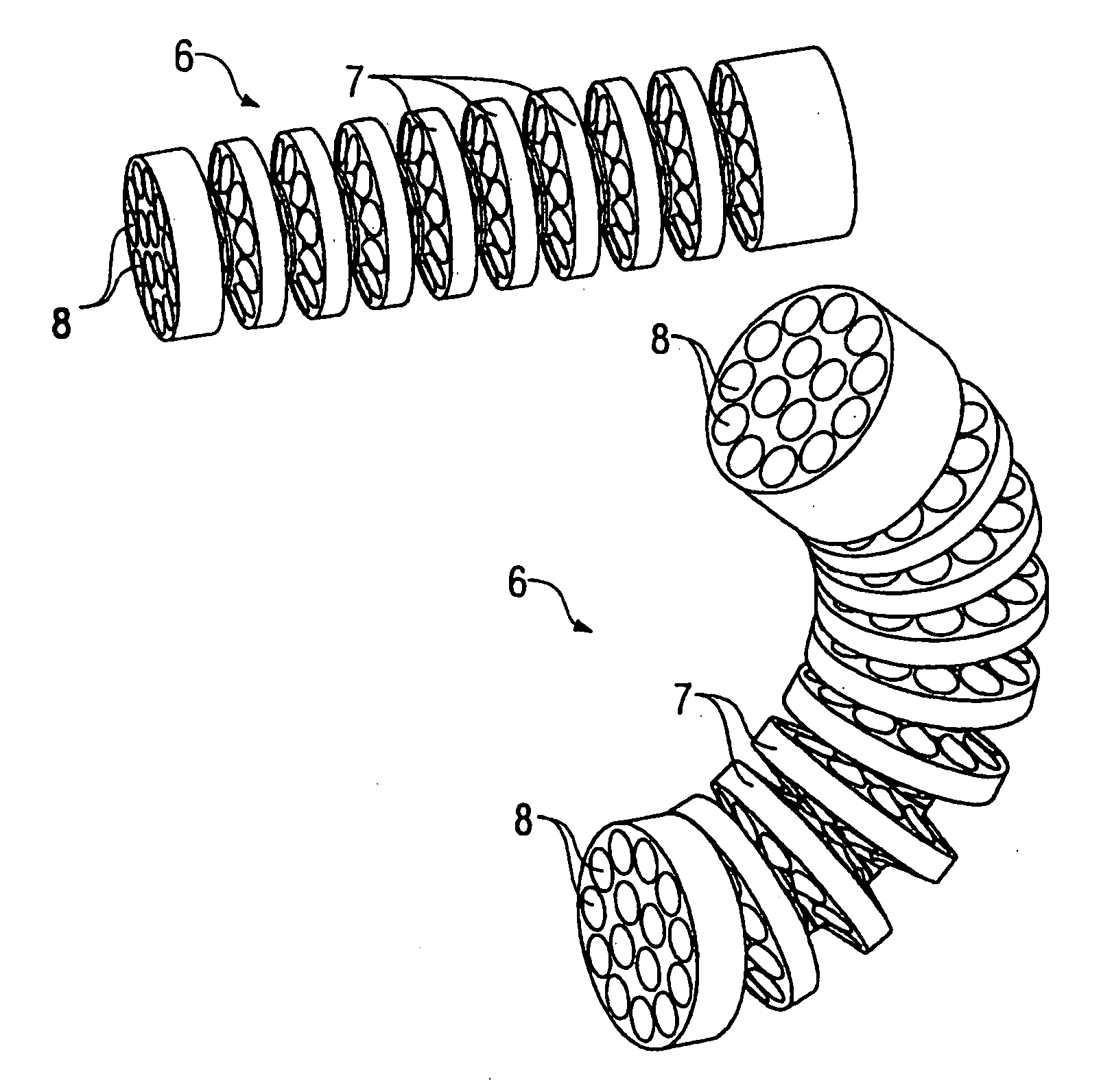
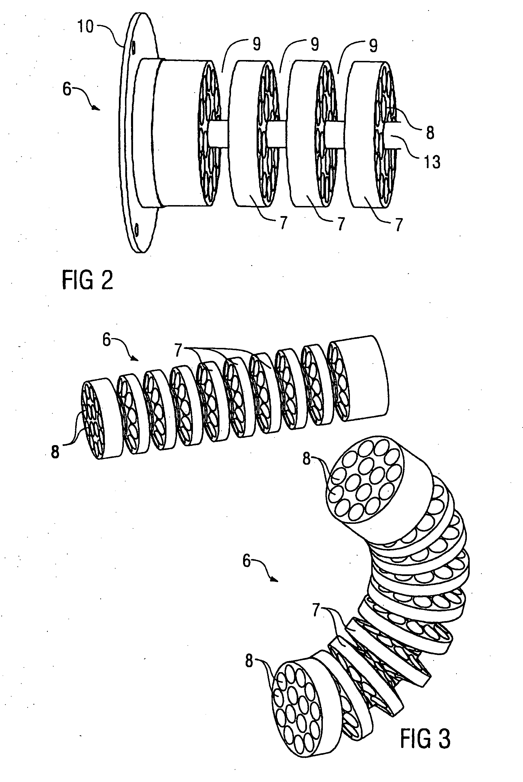
[0008] The invention disposes a special hose guiding element in the robot wrist axis, which element guides the hoses in the lateral direction and thereby prevents the formation of loops. The hose guiding element of the invention therefore has preferably at least one guide passage running axially to receive the hose to be routed, where the guide passage preferably goes completely through the hose guiding element in the axial direction. In one version of the invention the hose guiding element has several guide plates with a specified outside diameter located axially behind one another. In each of the several guide plates at least one guide passage is located for the hose to be routed, with the guide passages in the individual guide plates located in axial alignment. This offers the advantage that the hoses within the conduit are guided laterally not just at one point but preferably along the entire length of the conduit. Moreover, dividing the hose guiding element into several guide plates located axially one behind the other advantageously allows great bending flexibility in the hose guiding, which is particularly important in a robot wrist axis.
[0023] It should be mentioned further that the invention is not restricted to the previously described hose guiding element in accordance with the invention as a single component, but it also includes a hose conduit with a protective hose and a hose guiding element in accordance with the invention located therein. In this, the hose guiding element may be coated on the surfaces contacting the surrounding protective hose with a lubricant, such as Vaseline® petroleum jelly, to reduce friction and thus wear. The protective hose moreover is preferably oversize compared with the hose guiding element located inside, which further reduces friction and therefore wear.

Problems solved by technology

A disadvantage associated with each of these known versions of a hose conduit in a robot wrist axis is the fact that the hoses change their position in the hose conduit when the wrist axis bends or rotates.
There is a danger that as the result of axial stretching and compression loops form in the conduit, potentially becoming pinched in the rest of the hose bundle, thus bending and wearing very quickly.
Furthermore, the hoses can become twisted in different positions and then slide against each other under high pressure.

Method used


Image

  • Hose conduit element for a paint robot
  • Hose conduit element for a paint robot
  • Hose conduit element for a paint robot

Examples


Embodiment Construction

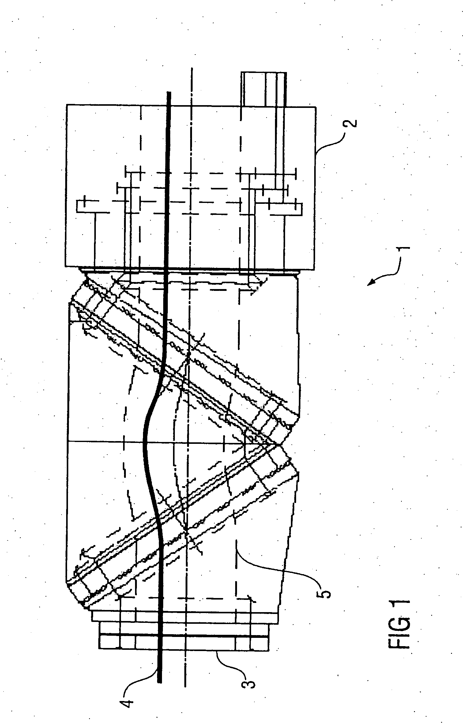
[0035] The side elevation in FIG. 1 shows a largely conventionally constructed robot wrist axis 1 of a painting robot. The robot wrist axis 1 is attached to a robot arm 2 of the painting robot and has an attaching flange 3 at its distal end to which, for example, a rotary atomizer can be attached.

[0036] Several hoses run through the robot wrist axis 1, with only a single hose 4 shown for the sake of simplicity. The hoses running through the robot wrist axis 1 carry, for example, coating agents or air to drive the rotary atomizer turbine. The hose 4 runs in a passageway 5 inside the wrist axis 1, where the routing of the hose 4 within the passageway 5 can be effected by a hose guiding element 6, as shown in FIGS. 2-5 or in FIGS. 6 and 7 and described in what follows.

[0037] The hose guiding element 6 has numerous disc-shaped guide plates 7, axially separated and located behind one another. Several guide passages 8 are distributed over the cross-section in which the hose 4, or the ad...


PUM

PropertyMeasurementUnit
Fractionaaaaaaaaaa
Fractionaaaaaaaaaa
Diameteraaaaaaaaaa

Abstract

A hose guiding element for routing at least one hose in a hose passageway of a robot. The hose guiding element has a least one guide passage running axially to receive the hose to be routed. The element has particular use in a wrist axis of a painting robot.

Description

CROSS-REFERENCE TO RELATED APPLICATIONS [0001] This application claims priority to U.S. Provisional Patent Application Ser. No. 60 / 686,319 filed on Jun. 1, 2005, the entire contents of which is incorporated herein in its entirety.FIELD OF THE INVENTION [0002] The invention relates in general to a hose element for guiding a hose in a hose conduit of a robot. DESCRIPTION OF THE RELATED ART [0003] On modern painting robots with a highly flexible robot wrist axis several hoses have to be passed through the robot arm and the wrist axis. The individual hoses supply, for example, the coating material to be applied or drive air to drive an atomizer turbine. Two versions known for routing hoses in the robot wrist axis are briefly described in what follows. [0004] In one version the robot wrist axis has rigid, mostly smoothly polished metal tubes, which may be straight or curved and which position the hoses. The transitions between the individual metal tubes should be as straight as possible ...

Claims


Application Information

Patent Timeline
IPC IPC(8): F16G13/00
CPCF16L3/01B25J19/0025Y10S59/90
Inventor MELCHER, RAINER
Owner DURR SYST INC
Learn More