Laser ablating of printing plates and/or printing rollers to decrease taper and TIR

a printing plate and printing roller technology, applied in the field of printing plates, can solve the problems of lack of adequate cylindricity, variations in cylindricity, and uneven taper of printing plates, so as to reduce variations in tir and/or taper, and ensure cylindricity

Inactive Publication Date: 2006-12-07
VAN DENEND MARK E
View PDF34 Cites 13 Cited by
  • Summary
  • Abstract
  • Description
  • Claims
  • Application Information

AI Technical Summary

Benefits of technology

[0009] It is another object of the present invention to provide an apparatus and method for laser ablating of printing rollers and / or printing plates thereon to decrease variations in TIR and / or TAPER thereof in order to ensure cylindricity thereof.
[0024] In one embodiment, the printing roller includes a cylindrical roller, and the step of laser ablating includes the step of reducing at least one of total indicated run-out and taper by ablating a surface of the cylindrical roller. In such case, there is the further step of laser ablating an image into the cylindrical roller.

Problems solved by technology

However, a problem with such known arrangements is that the raised surface of the printing plate, when mounted on the printing roller, is not adequately cylindrical.
However, tolerances in the printing roller and / or the printing plate cause variations in the cylindricity.
In other words, these tolerances result in a lack of adequate cylindricity.
However, in regions of the printing roller and printing plate having a greater radius than other regions, this results in various problems, such as general squeegeeing of the image, printing plate speed mismatch and a resultant general lower quality print.
However, this is burdensome, costly and time consuming.

Method used


Image

  • Laser ablating of printing plates and/or printing rollers to decrease taper and TIR
  • Laser ablating of printing plates and/or printing rollers to decrease taper and TIR
  • Laser ablating of printing plates and/or printing rollers to decrease taper and TIR

Examples


second embodiment

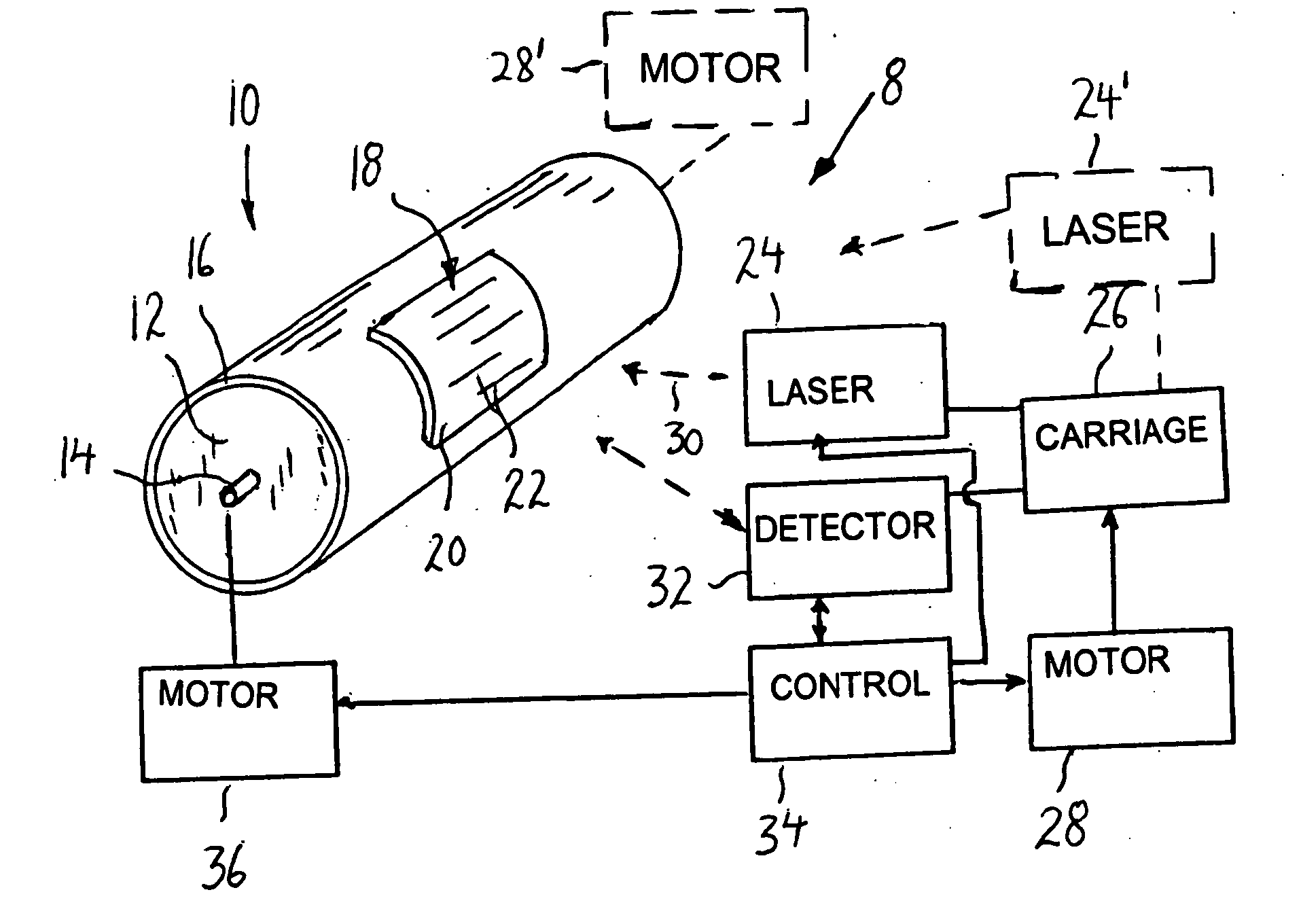
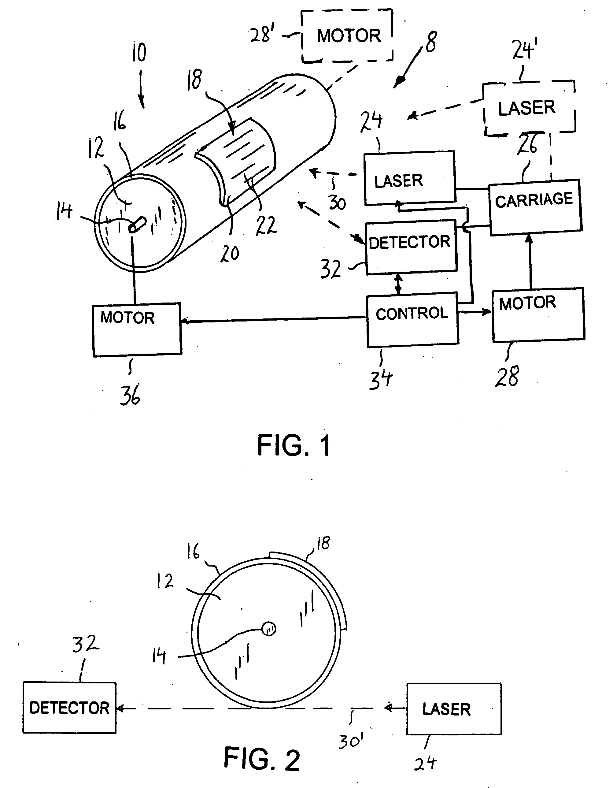
[0054] In a second method of the present invention, and referring again to FIGS. 1-3, if printing plate 18 does not have a uniformly constant thickness throughout, then it is necessary to also ablate printing plate 18 to reduce variations in TIR and / or TAPER in order to ensure the cylindricity of the outer surface thereof when mounted on sleeve 16. Specifically, as shown in FIG. 7, sleeve 16 is mounted on cylindrical roller 12 in step 200. Then, the cylindricity of sleeve 16 in regard to variations in TIR and / or TAPER is measured in step 202 by detector 32. From these measurements, the portions of the outer surface of sleeve 16 that need to be ablated in order to reduce variations in TIR and / or TAPER to ensure cylindricity thereof are determined in step 204 by control device 34. Laser 24 then ablates those portions of the outer surface of sleeve 16 in order to reduce variations in TIR and / or TAPER to ensure cylindricity, in step 206. In step 206, there is preferably relative longitu...

third embodiment

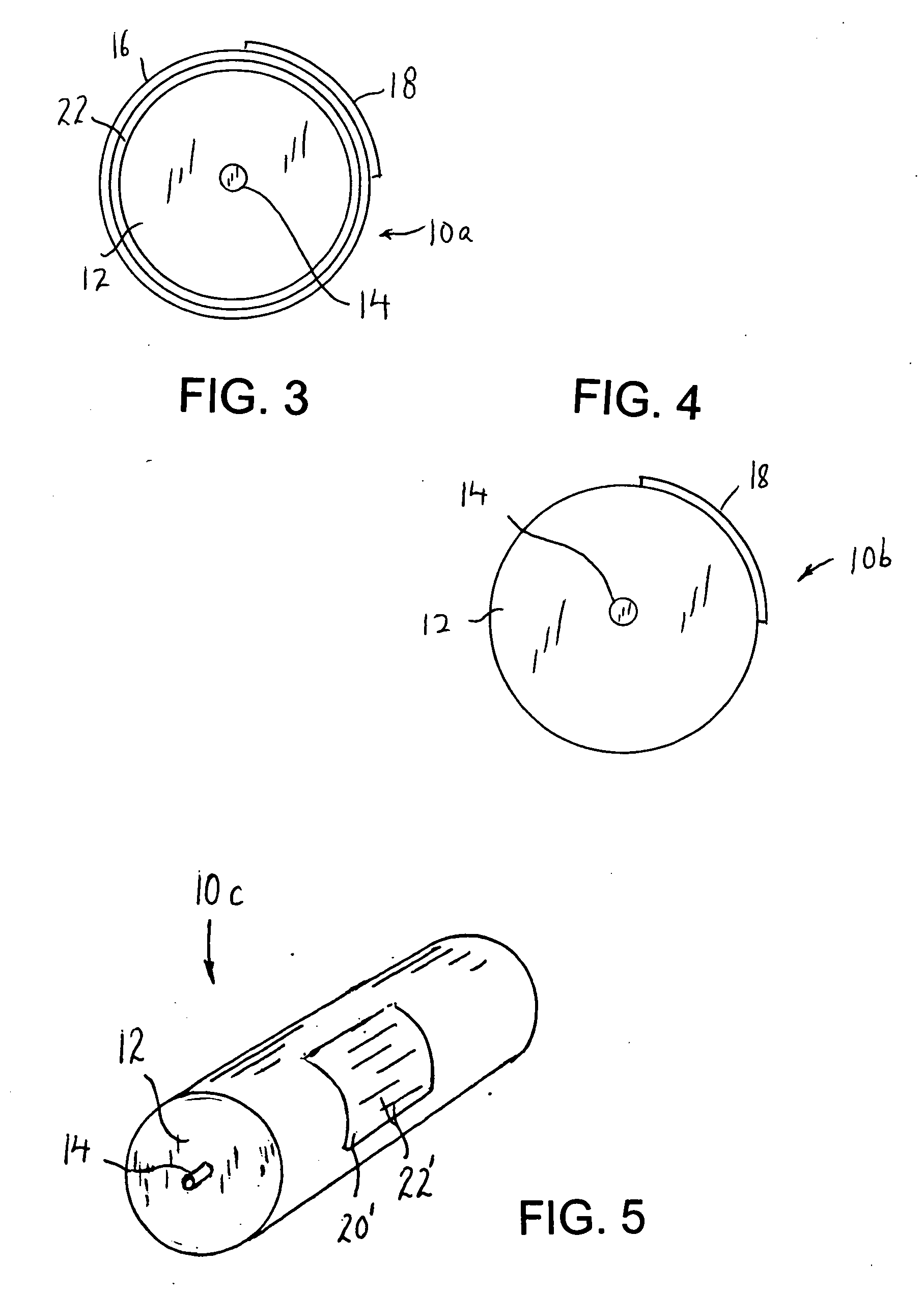
[0057] Alternatively, in a third method of the present invention shown in FIG. 8, if the thickness of printing plate 18 is not uniformly constant throughout, it is possible to eliminate the steps relating to ablating of cylindrical roller 12 and sleeve 16, and in such case, only ablate printing plate 18 in order to reduce variations in TIR and / or TAPER to achieve cylindricity of the outer surface of printing plate 18 mounted on sleeve 16. Specifically, sleeve 16 is mounted on cylindrical roller 12 in step 300. In such case, cylindrical roller 12 and / or sleeve 16 may or may not have variations in TIR and / or TAPER, and may not be adequately cylindrical. Then, in step 302, printing plate 18 is mounted to the outer surface of sleeve 16 in a conventional manner. In step 304, the cylindricity of printing plate 18 in regard to TIR and / or TAPER is measured by detector 32. From these measurements, the portions of the raised or outer surface 20 of printing plate 18 that need to be ablated in ...


PUM

PropertyMeasurementUnit
electromagnetic spectrumaaaaaaaaaa
relative movementaaaaaaaaaa
radiiaaaaaaaaaa

Abstract

Apparatus for reducing variations in total indicated run-out and taper in a printing roller, includes a detector which detects variations in total indicated run-out and taper in a surface of the printing roller, and a laser which ablates the surface of the printing roller. A control device controls the laser to ablate the surface in a manner to reduce variations in the total indicated run-out and taper in the printing roller, in response to the detector, while there is relative rotation and lengthwise movement between the printing roller and the laser and detector. Also, a printing plate is mounted on the printing roller, and the control device controls the laser to reduce the total indicated run-out and taper by further ablating a surface of the printing plate. The control device further controls the laser to etch an image into the printing plate.

Description

BACKGROUND OF THE INVENTION [0001] The present invention relates generally to printing plates mounted on cylindrical rollers in a printing press, and more particularly, is directed to an apparatus and method for laser ablating of printing plates and / or printing rollers to decrease variations in TIR and / or TAPER thereof in order to ensure cylindricity thereof. [0002] It is well-known to use printing plates mounted on printing rollers in a printing operation. The printing rollers can include one or more sleeves and / or other layers thereon. The printing plates are etched or engraved in accordance with a desired image in order to effect the printing operation. It is also known to provide such etching or engraving of the image on the printing plate by means of a laser. [0003] However, a problem with such known arrangements is that the raised surface of the printing plate, when mounted on the printing roller, is not adequately cylindrical. In other words, apart from the etched portions, t...

Claims


Application Information

Patent Timeline
Patent Type & Authority Applications(United States)
IPC IPC(8): B41C3/08
CPCG03F7/40B41C1/05
Inventor VAN DENEND, MARK E.
Owner VAN DENEND MARK E
Why Eureka
Try Eureka