
Electric connection element

a technology of electric connection element and connection contact, which is applied in the direction of connection contact member material, coupling contact member, electrical apparatus, etc., can solve the problems of insufficient heating of coating, insufficient reliability of connection between electric conductor and electric component, and significant energy amount required to heat up coating fast enough, etc., to achieve special rapid heating and comparably low energy consumption

Inactive Publication Date: 2006-12-07
OUTOKUMPU COPPER NEUMAYER
View PDF2 Cites 10 Cited by
  • Summary
  • Abstract
  • Description
  • Claims
  • Application Information

AI Technical Summary

Benefits of technology

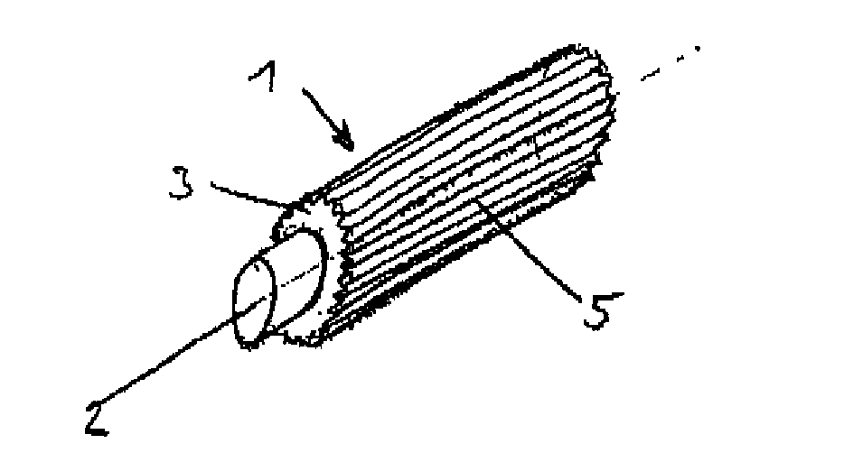
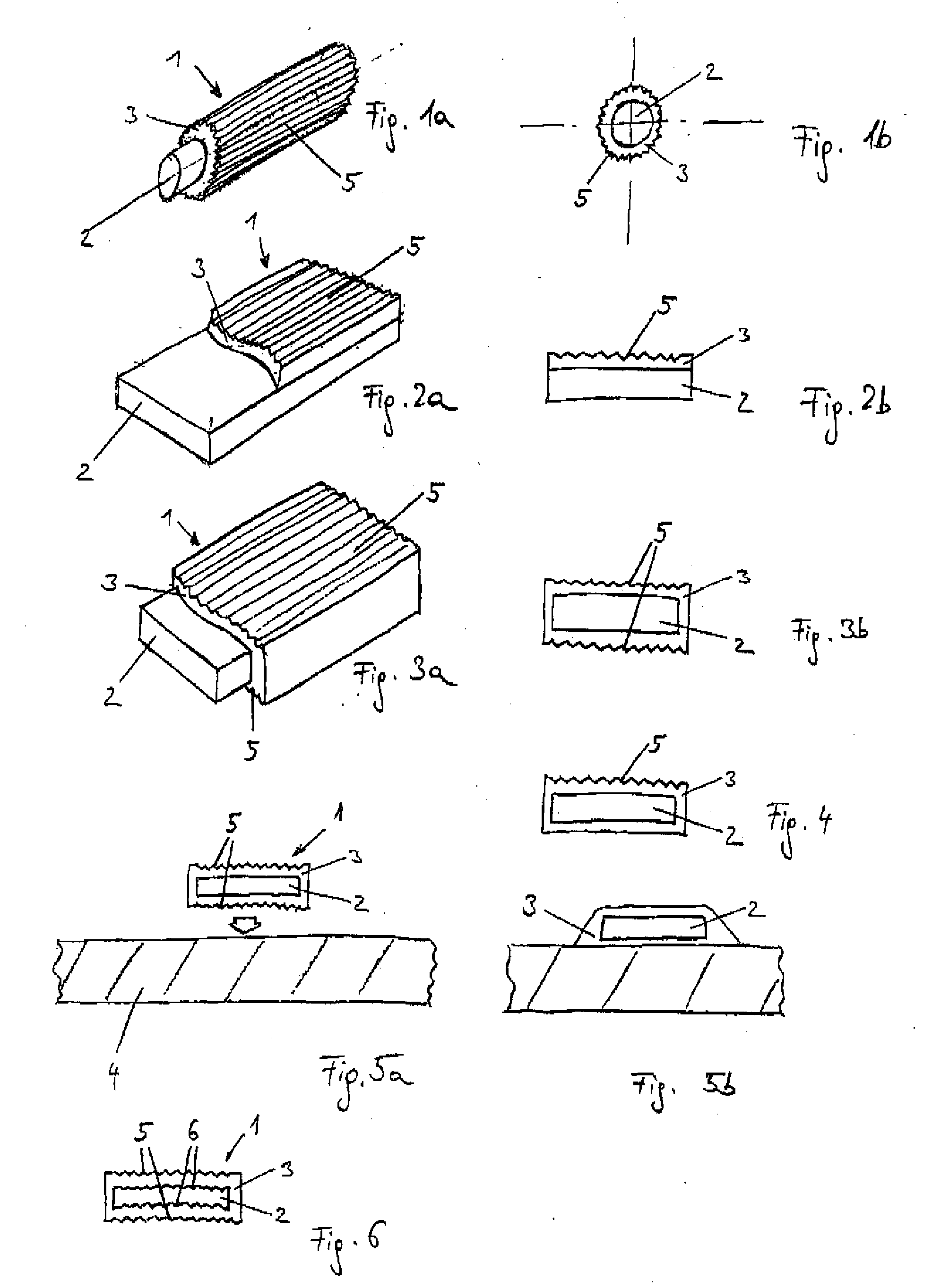
[0009] The present invention resolves prior art problems by enlarging the surface area of the coating to effect increased light and / or heat absorption. Heat required for a soldering or bonding process can thus be introduced easier and faster. Currently preferred is the formation of the surface enlargement as integral part of the coating. In other words, the coating material itself is modified in a way to realize an enlarged surface area, without adding foreign matter.
[0031] According to another feature of the present invention, the surface enlargement may be realized by providing the coating surface with a structuring and / or roughening the surface of the coating.

Problems solved by technology

Common to all conventional connection elements is the drawback that significant energy amounts are required to heat up the coating fast enough.
As a result, the coating cannot be quickly heated up sufficiently so that a reliable connection between an electric conductor and the electric component is not ensured.

Method used


Image

  • Electric connection element
  • Electric connection element
  • Electric connection element

Examples


Embodiment Construction

[0047] Throughout all the Figures, same or corresponding elements are generally indicated by same reference numerals. These depicted embodiments are to be understood as illustrative of the invention and not as limiting in any way. It should also be understood that the drawings are not necessarily to scale and that the embodiments are sometimes illustrated by graphic symbols, phantom lines, diagrammatic representations and fragmentary views. In certain instances, details which are not necessary for an understanding of the present invention or which render other details difficult to perceive may have been omitted.

[0048] This is one of two applications both filed on the same day. Both applications deal with related inventions. They are commonly owned and have the same inventive entity. Both applications are unique, but incorporate the other by reference. Accordingly, the following U.S. patent application, based on U.S. provisional Application No. 60 / 686,184, filed Jun. 1, 2005, entitl...


PUM


Abstract

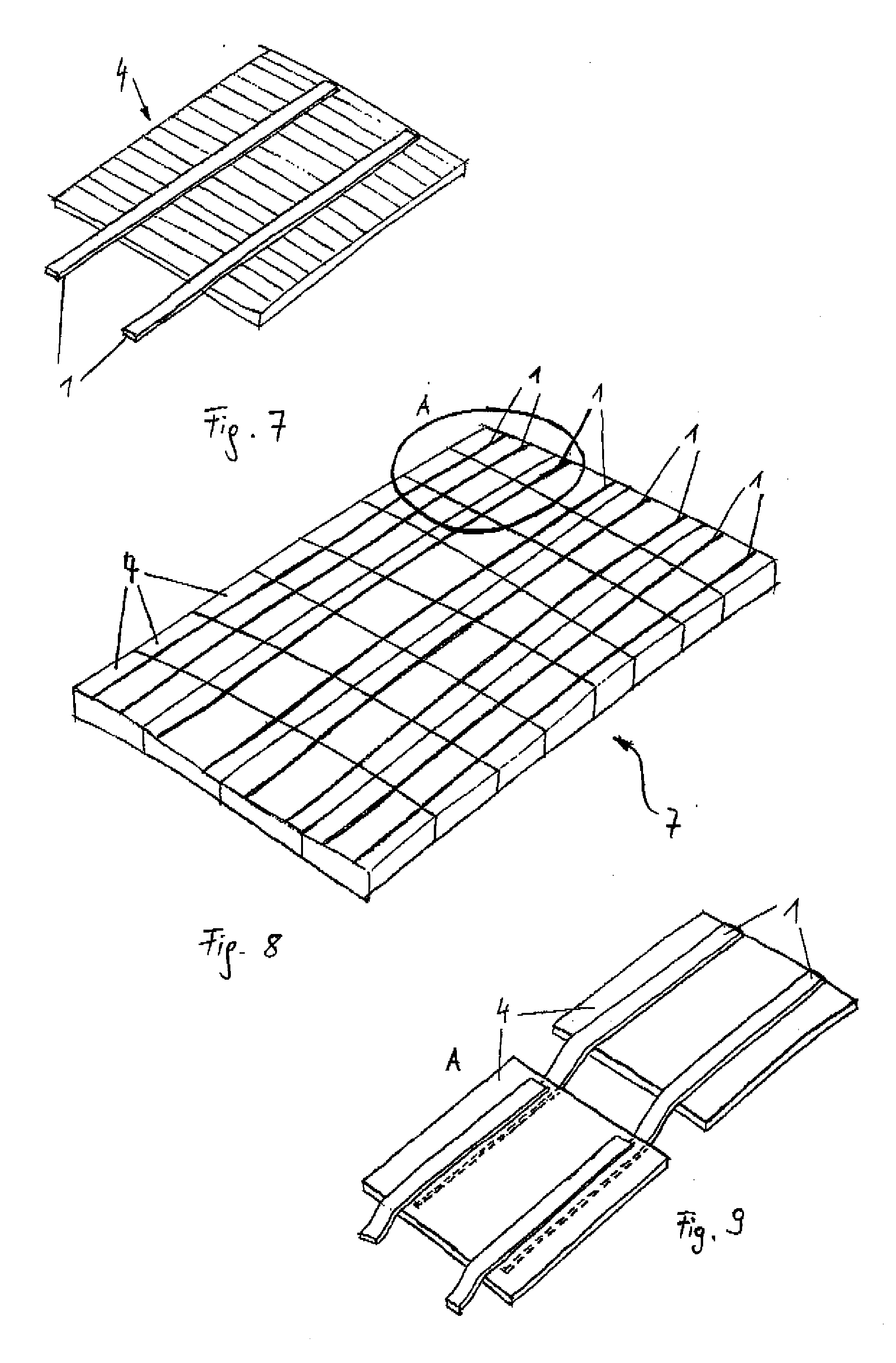
An electric connection element includes an electric conductor, and an electrically conductive coating which is applied onto the conductor and has, at least in regions thereof, a structuring and / or rough surface. As a result, the connection element can easily be handled and the coating can be quickly heated.

Description

CROSS-REFERENCES TO RELATED APPLICATIONS [0001] This application claims the benefit of prior filed U.S. provisional Application No. 60 / 686,185, filed Jun. 1, 2005, pursuant to 35 U.S.C. 119(e), the content of which is incorporated herein by reference. [0002] This application also claims the priority of Austrian Patent Application, Serial No. A 939 / 2005, filed Jun. 1, 2005 pursuant to 35 U.S.C. 119(a)-(d), the content of which is incorporated herein by reference.BACKGROUND OF THE INVENTION [0003] The present invention relates, in general, to an electric connection element for connecting electric components. [0004] Connection elements of a type involved here have been used to electrically interconnect several electric components, e.g. solar cells, and are constructed in the form of a flat wire as electric conductor which has a coating of solder material. As the connection element is heated to melt the coating, it is soldered with the electric component. Coated connection elements desi...

Claims


Application Information

Patent Timeline
Patent Type & Authority Applications(United States)
IPC IPC(8): H01R4/18
CPCH01R4/024H01R13/03H01R4/26
Inventor BERGHOFER, PETERSUGETICH, JOSEFPEDEVILLA, MATHIAS
Owner OUTOKUMPU COPPER NEUMAYER
Learn More