Jounce bumper, rate cup, and strut mount bottom plate

a bumper and bottom plate technology, applied in the direction of shock absorbers, mechanical equipment, transportation and packaging, etc., can solve the problems of lower side load of rod guides and bearings, and achieve the effect of large angular travel

Inactive Publication Date: 2006-12-07
FREUDENBERG NOK GEN PARTNERSHIP
View PDF33 Cites 10 Cited by
  • Summary
  • Abstract
  • Description
  • Claims
  • Application Information

AI Technical Summary

Benefits of technology

[0002] Jounce bumpers are often mounted on a strut assembly where a jounce bumper surrounds a strut rod of a strut suspension. The jounce bumper prevents the cylinder of the strut assembly from heavily impacting the strut mounting assembly. A strut rod that has a large angular travel and a fixed rate cup requires a jounce bumper and striker that are smaller in diameter than a jounce bumper and striker where the strut rod has little or no angular travel.
[0003] Accordingly, the present invention provides a rate cup that moves with the strut rod so as to allow use of a larger jounce bumper and striker in applications where the strut rod has a larger angular travel. The larger jounce bumper and striker result in lower stress levels in the jounce bumper. Lower stress levels result in improved durability and performance. An additional advantage of a rate cup that moves with the strut rod is that the striker is able to directly contact the jounce bumper without an angular offset. The jounce bumper is not likely to bulge out from between the striker and rate cup when there is no angular offset. This results in more consistent jounce bumper performance when comparing load versus deflection.
[0004] Also, by contacting the jounce bumper with no angular offset, the striker is subjected to lower side loads which results in lower side loads to the rod guide and bearing. Lower side loads at the rod guide and bearing result in less friction in the strut assembly and, therefore, smoother strut performance. The design also allows the rate cup and jounce bumper to move with the angular travel of the strut rod, but it does not transmit jounce loads to the strut rod and into the elastomeric component of the strut mount. Therefore, the elastomeric component of the strut mount does not have to be designed to support jounce loads. The strut mount will be less costly, provide better noise vibration and harshness performance, and better durability. With the jounce bumper rate cup that is mounted on the strut rod, free to slide along the strut rod and free to move relative to the strut mount, the upper end of the rate cup, according to the principles of the present invention, is spherical as opposed to a typical design which is flat, with the concave side toward the strut mount. The center of the spherical surface is located at the center of oscillation of the strut rod. A strut mount bottom plate or upper spring seat that is part of the strut mount assembly is spherical, with the convex side toward the rate cup and concentric with the spherical surface of the rate cup. The jounce bumper is mounted onto the strut rod and inside the rate cup. A disk of elastomeric material is installed between the rate cup and the strut mount bottom plate or upper spring seat to prevent the rate cup and strut mount bottom plate or upper spring seat from hitting each other and causing noise or damage to each other.

Problems solved by technology

Also, by contacting the jounce bumper with no angular offset, the striker is subjected to lower side loads which results in lower side loads to the rod guide and bearing.

Method used


Image

  • Jounce bumper, rate cup, and strut mount bottom plate
  • Jounce bumper, rate cup, and strut mount bottom plate
  • Jounce bumper, rate cup, and strut mount bottom plate

Examples


Embodiment Construction

[0011] The following description of the preferred embodiment(s) is merely exemplary in nature and is in no way intended to limit the invention, its application, or uses.

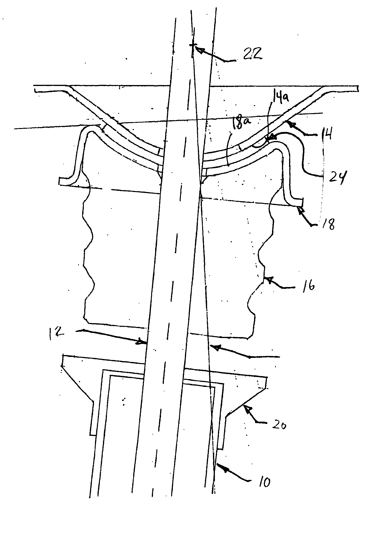
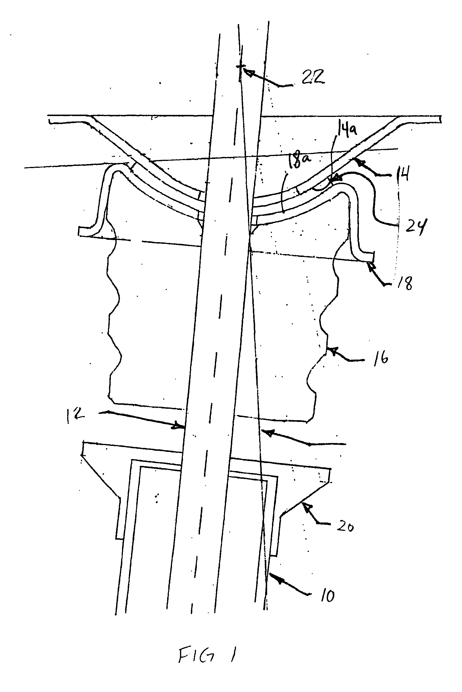
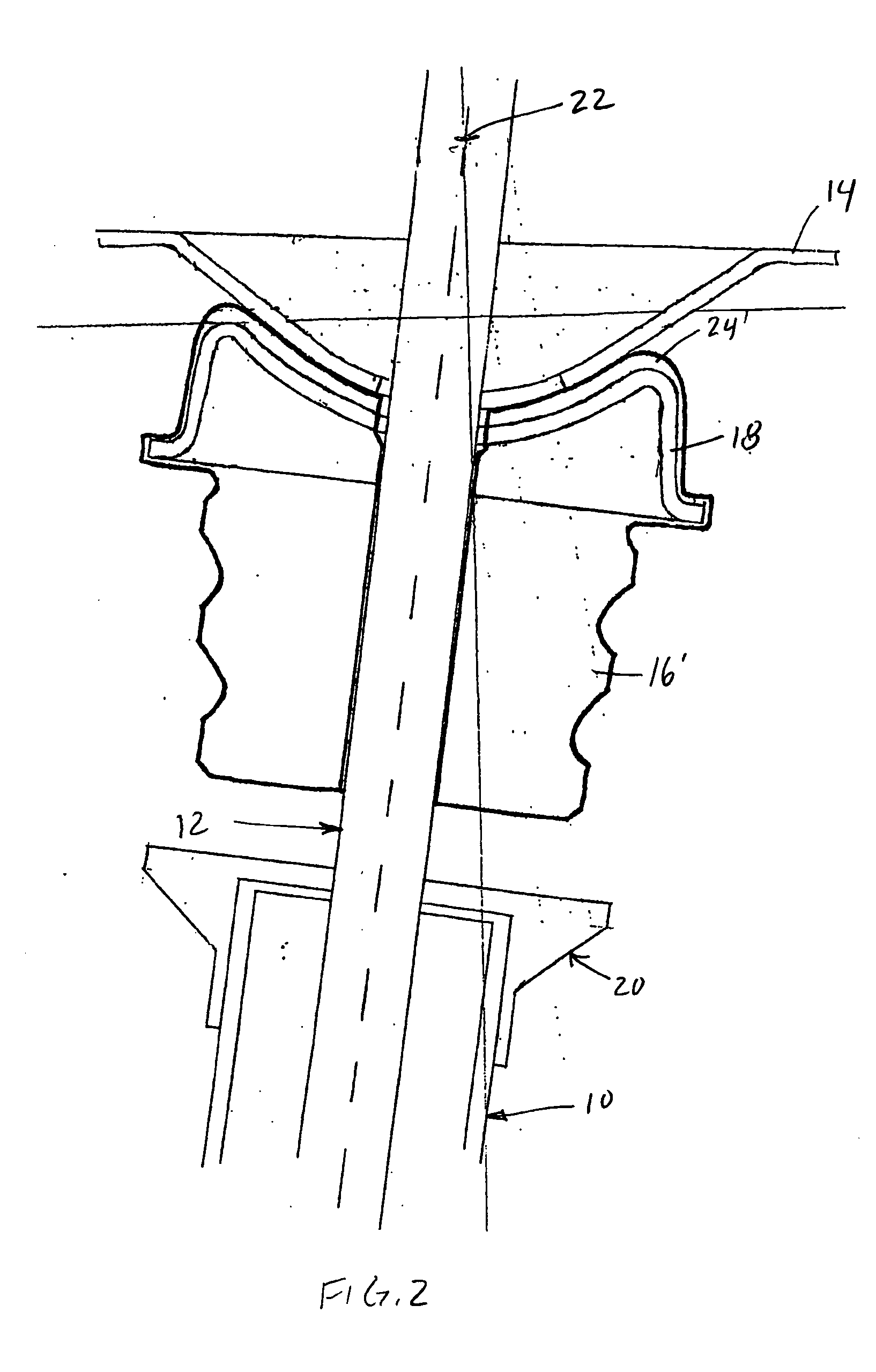
[0012] With reference to FIG. 1, a shock absorber tube 10 of a vehicle suspension system is shown including a strut rod 12 extending therefrom. Strut rod 12 is adapted to be mounted to a strut mount. As is known in the art, the strut mount includes a top plate, bottom plate, and an elastomeric element disposed therebetween to which the strut rod 12 is mounted. Optionally, the strut mount can also include a spring seat and bearing mounted to the bottom plate of the strut mount. As illustrated in FIGS. 1-4, reference numeral 14 is an illustration of the lowermost portion of the strut mount which can include a bottom plate of the strut mount or, if included, the spring seat of a spring seat and bearing assembly. Accordingly, throughout this application, reference numeral 14 is used to reference “the strut mount bottom ...


PUM


Abstract

A strut and jounce bumper assembly is provided including a rate cup and jounce bumper that are capable of moving with the strut rod wherein the rate cup is provided with a concave spherical upper surface that engages a convex spherical surface of a strut mount bottom plate. The design allows use of a larger jounce bumper and striker in applications where the strut rod has large angular travel.

Description

FIELD OF THE INVENTION [0001] The present invention relates to suspension systems for motor vehicles, and more particularly to a jounce bumper, rate cup, and strut mount bottom plate or upper spring seat for a strut module having a large angular travel of the strut rod. BACKGROUND AND SUMMARY OF THE INVENTION [0002] Jounce bumpers are often mounted on a strut assembly where a jounce bumper surrounds a strut rod of a strut suspension. The jounce bumper prevents the cylinder of the strut assembly from heavily impacting the strut mounting assembly. A strut rod that has a large angular travel and a fixed rate cup requires a jounce bumper and striker that are smaller in diameter than a jounce bumper and striker where the strut rod has little or no angular travel. [0003] Accordingly, the present invention provides a rate cup that moves with the strut rod so as to allow use of a larger jounce bumper and striker in applications where the strut rod has a larger angular travel. The larger jou...

Claims


Application Information

Patent Timeline
Patent Type & Authority Applications(United States)
IPC IPC(8): B60G13/00F16F9/00
CPCB60G2202/143B60G2202/24F16F9/58B60G2204/416B60G2204/4502B60G2204/125
Inventor FELDMANN, ROBERT STUART
Owner FREUDENBERG NOK GEN PARTNERSHIP
Why Eureka
Try Eureka