Optical element and optical pickup

a technology of optical elements and pickups, applied in the field of optical elements, can solve the problems of degrading the characteristics of these optical elements and degrading the optical characteristics, and achieve the effects of avoiding the influence of conductors, avoiding degradation of optical elements' characteristics, and correcting various kinds of aberration

Inactive Publication Date: 2006-12-07
KONICA MINOLTA INC
View PDF1 Cites 69 Cited by
  • Summary
  • Abstract
  • Description
  • Claims
  • Application Information

AI Technical Summary

Benefits of technology

[0035] In this structure, of the individual electrodes formed on one side of the liquid crystal layer, the one closest to the liquid crystal layer is so formed as to be continuous within the optical path. Thus, simply by forming this individual electrode so that a part thereof protrudes out of the optical path, it is possible to provide, outside the optical path, a conductor for applying a voltage to that individual electrode so that the voltage can be applied to the entire individual electrode. Thus, in this case, there is no need to provide the conductor within the optical path. This helps eliminate the influence of the conductor on the electric field distribution, and helps produce an ideal electric field distribution. As a result, it is possible to avoid degradation of the characteristics of the optical element attributable to the conductor.
[0036] Moreover, the above-mentioned individual electrode has a hole within the optical path, and thus, by varying the electric field distribution according to where to form the hole, it is possible to correct various kinds of aberration. Specifically, for example, forming the hole so that the center thereof coincides with the optical axis makes it possible to correct spherical aberration; forming the hole in a position corresponding to a peak of coma makes it possible to correct coma.
[0037] Moreover, the above-mentioned individual electrode has a transparent part within the optical path. This helps avoid a lowering in the transmissivity of the individual electrode to the light transmitted therethrough.
[0038] According to still another aspect of the present invention, an optical pickup is provided with an optical element, like one of those described above, according to the present invention. Since an optical element according to the present invention helps avoid degradation of characteristics resulting from disturbance in an electric field distribution attributable to conductors, incorporating one in an optical pickup helps enhance the accuracy with which information is recorded to and reproduced from an optical recording medium.

Problems solved by technology

This causes the pattern of the Fresnel zone plate that is produced on the liquid crystal panel to be deformed from the ideal concentric shape, and may thus lead to degraded optical characteristics.
Disadvantageously, this degrades the characteristics of these optical elements.

Method used


Image

  • Optical element and optical pickup
  • Optical element and optical pickup
  • Optical element and optical pickup

Examples


first embodiment

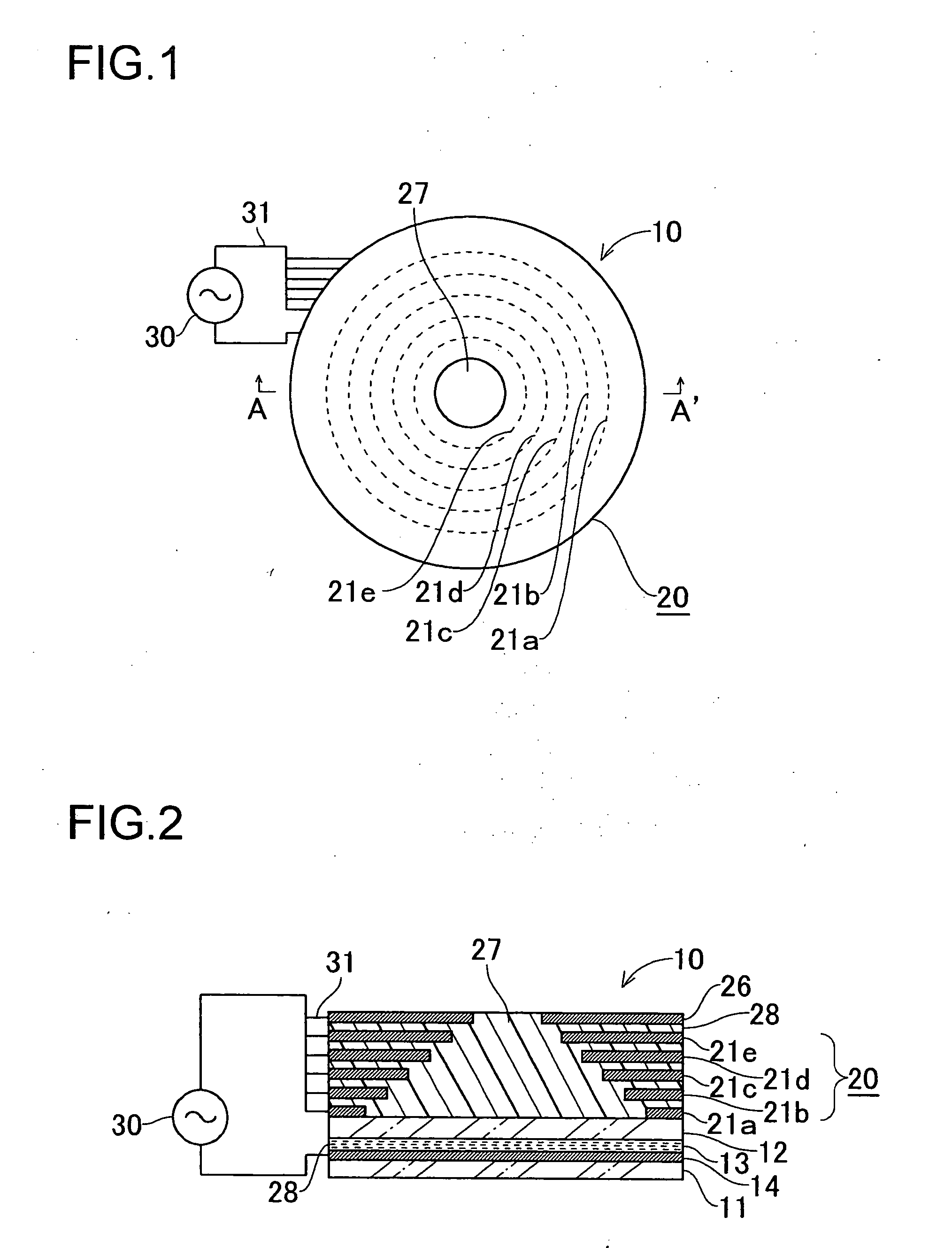
[0075] A first embodiment of the present invention will be described below with reference to the relevant drawings. FIG. 1 is a plan view of the optical element of the first embodiment, and FIG. 2 is a cross-sectional view thereof alone line A-A′ shown in FIG. 1 as viewed in the arrow-indicated direction.

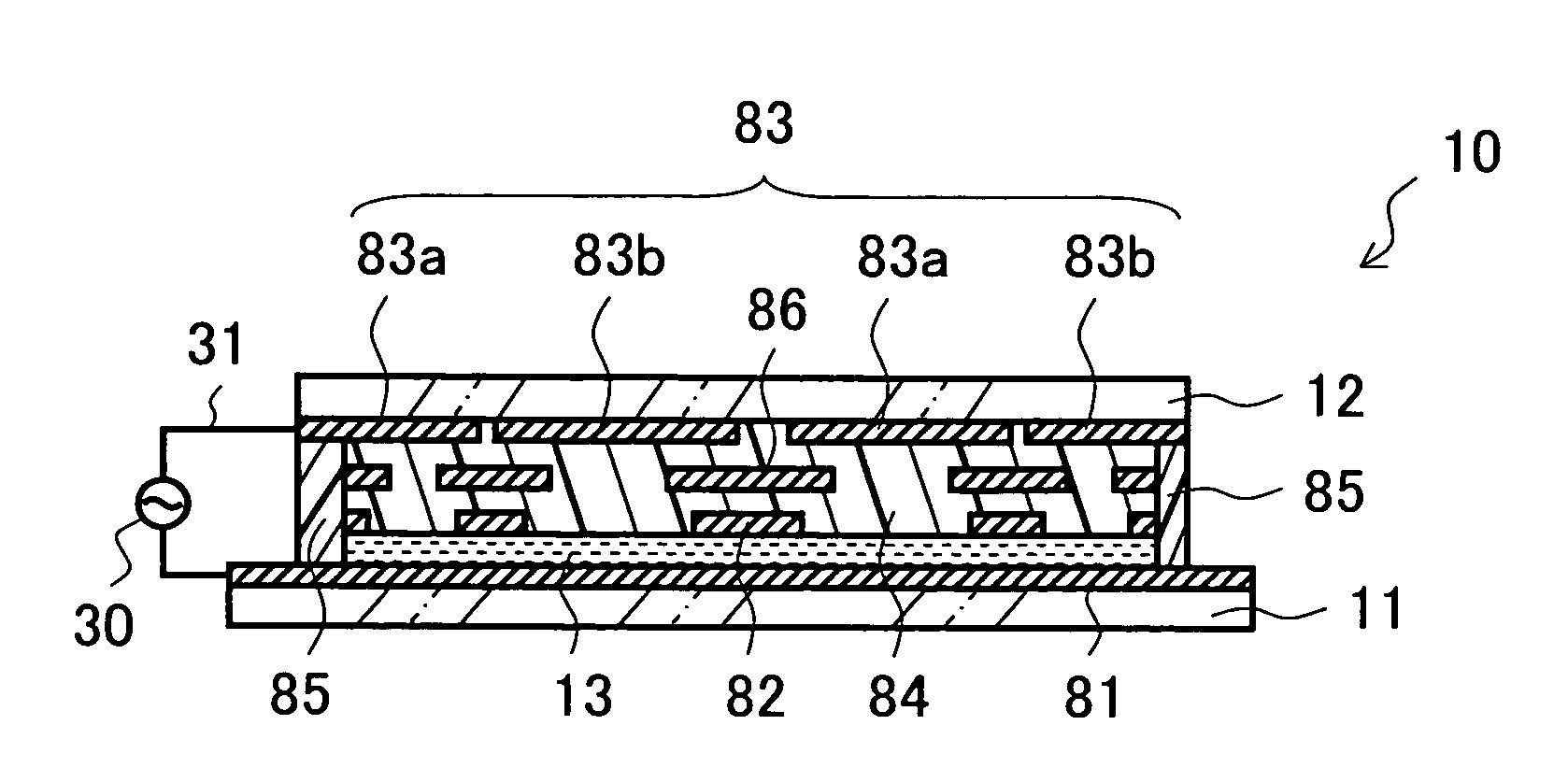
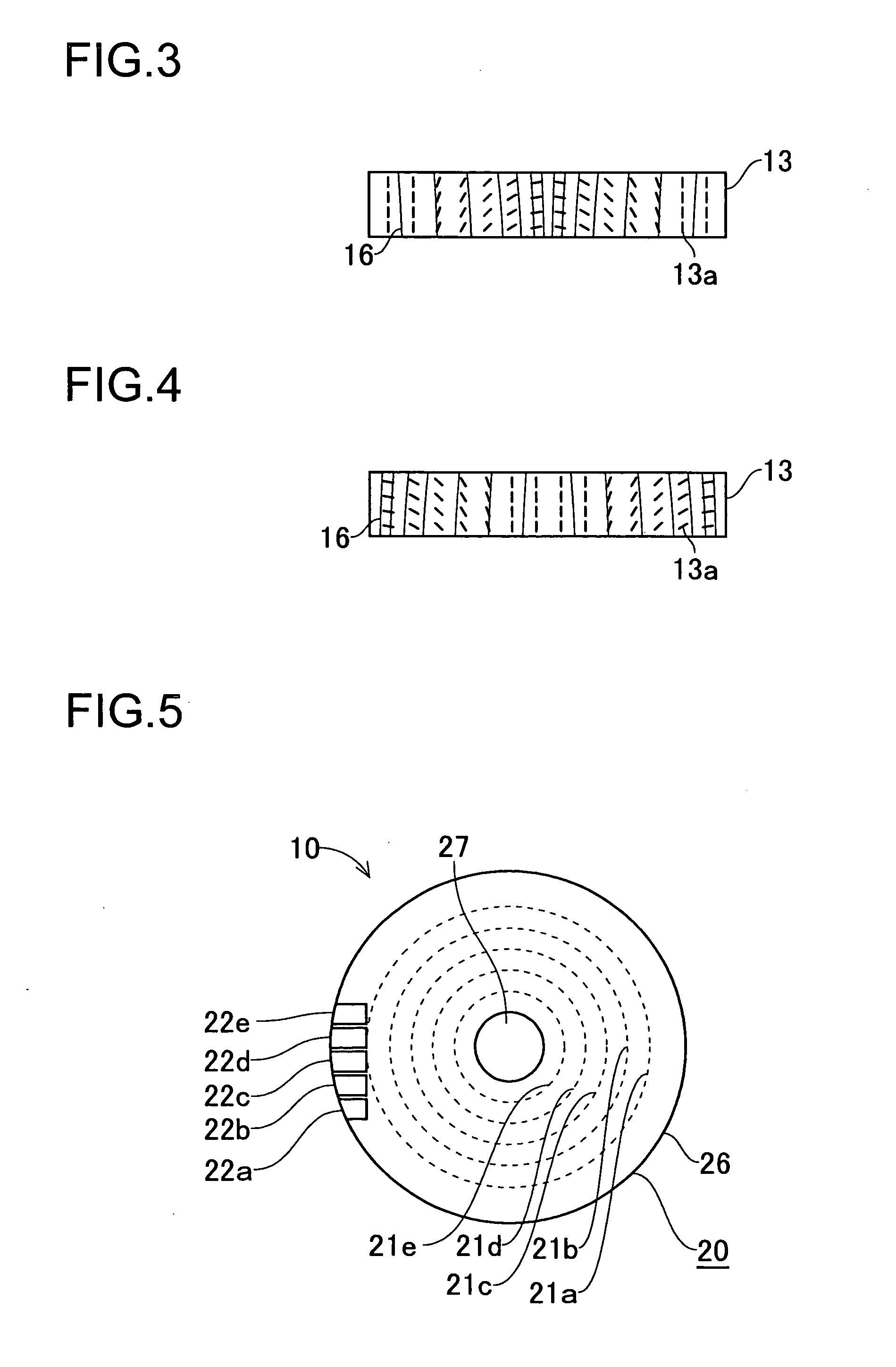
[0076] First, the structure of the optical element 10 will be described. As shown in FIGS. 1 and 2, in the optical element 10, a first transparent substrate 11 and a second transparent substrate 12 that have equal exterior diameters and are circular in shape are arranged to face each other at a distance from each other, with a liquid crystal layer 13 sealed in between. Over the entire surface of the first transparent substrate 11 facing toward the liquid crystal layer 13, a first electrode 14 that is transparent is laid.

[0077] On the surface of the second transparent substrate 12 facing away from the liquid crystal layer 13, a second electrode 20 is laid. The second electrode 20 i...

second embodiment

[0101] A second embodiment of the present invention will be described below with reference to the relevant drawings. FIG. 11 is a cross-sectional view of the optical element of the second embodiment. The second embodiment differs from the first embodiment in that, instead of the first electrode, a fourth electrode and a fifth electrode are provided; in other respects, the second embodiment is the same as the first embodiment, and therefore, in FIG. 11, such parts that find substantially equivalent parts in the first embodiment are identified by common reference numerals.

[0102] In the optical element 10 of the second embodiment, as shown in FIG. 11, on the surface of the first transparent substrate 11 facing away from the liquid crystal layer 13, a fourth electrode 41 and a fifth electrode 42 are laid that have the same structures as the second electrode 20 and the third electrode 26, respectively. It should be noted that what is referred to as a first, a second, a third, and a four...

third embodiment

[0105] A third embodiment of the present invention will be described below with reference to the relevant drawings. Such parts as find their counterparts in the first or second embodiment will be identified by common reference numerals, and no explanation thereof will be repeated.

[0106] First, a description will be given of the construction of an optical pickup to which the optical element 10 of each embodiment is applicable.

[0107]FIG. 12 is a diagram illustrating an outline of the construction of the optical pickup dealt with in this embodiment. This optical pickup is provided with: light sources 61, 62, and 63; beam splitters 64, 65, and 66; a collimator lens 67; an adjustment lens 68; a collimator lens 69; a half-mirror 70, a quarter-wave plate 71, a condenser lens (objective lens) 72; and photosensors 73 and 74. In this optical pickup, the optical element 10 is arranged in the optical path between the half-mirror 70 and the quarter-wave plate 71. The optical element 10 is desi...


PUM

PropertyMeasurementUnit
wavelengthaaaaaaaaaa

Abstract

On one side of a liquid crystal layer, a first electrode is provided, and, on the other side of the liquid crystal layer, a second electrode, composed of a plurality of individual electrodes, and a third electrode are provided. The second and third electrodes have holes that are increasingly small away from the liquid crystal layer. When the potential at the third electrode is set equal to or lower than the potential at the second electrode, the liquid crystal layer acts as a convex lens; when the potential at the third electrode is set higher than the potential at the second electrode, the liquid crystal layer acts as a concave lens. The range in which the focal length can be varied depends on the diameters of the holes, and giving the holes of the different electrodes varying diameters helps widen the range. Moreover, conductors can be laid to reach the electrodes at the outer edges thereof so as not to directly face the liquid crystal layer. This helps eliminate the influence of the conductors on the electric field distribution in the liquid crystal layer.

Description

[0001] This application is based on Japanese Patent Application No. 2005-166563 filed on Jun. 7, 2005 and Japanese Patent Application No. 2005-354449 filed on Dec. 8, 2005, the contents of both of which are hereby incorporated by reference. BACKGROUND OF THE INVENTION [0002] 1. Field of the Invention [0003] The present invention relates to an optical element using a liquid crystal, and to an optical pickup incorporating such an optical element. [0004] 2. Description of Related Art [0005] A liquid crystal that has dielectric constant anisotropy exhibits electric field dependence; that is, it varies its molecular alignment according to the directions of electric force lines. Thus, as the electric field is controlled, the optical characteristics of the liquid crystal can be controlled. This has led to proposals of various optical elements using liquid crystals. [0006] Patent Document 1, listed below, proposes a variable-focus optical system wherein, as shown in FIG. 28, ring-shaped ele...

Claims


Application Information

Patent Timeline
Patent Type & Authority Applications(United States)
IPC IPC(8): C09K19/34
CPCG02B3/14G02F1/134309G11B7/13925G11B7/1369G02F2001/294G02F1/294
Inventor HIROSE, SATORU
Owner KONICA MINOLTA INC
Why Eureka
Try Eureka