
Wheel guidance

a technology of wheel guide and bearing, which is applied in the direction of suspension arms with a strong grip, interconnection systems, and suspensions that are resilient, can solve the problems of damping a major part of the oscillation of wheel guide, and adversely affecting riding comfor

Inactive Publication Date: 2006-12-07
BENTELER AUTOMOBILTECHNIK GMBH
View PDF34 Cites 49 Cited by
  • Summary
  • Abstract
  • Description
  • Claims
  • Application Information

AI Technical Summary

Benefits of technology

[0012] The present invention resolves prior art problems by constructing an active arrangement with several linear motors that operate in separate directions. In this way, the active arrangement is able to suit the chassis during travel to road and traffic conditions at hand as well as to the properties of the vehicle. This can be realized in particular by altering the chassis manipulations, such as track values for example. Oscillation of the trailing arm or wishbone during travel can be detected by a sensor assembly and damped by an actively generated compensation oscillation to effectively neutralize or shift the oscillation to a higher frequency range in particular. The active arrangement adapts and intervenes actively to generate static as well as periodic shifts of a bearing axis for example. Static shifts cause track adjustment whereas periodic shifts in suitable phase position effect a suppression of oscillations or a frequency damping. In addition, the active arrangement is able to uncouple the wheel guidance from the vehicle body so that this measure provides also an effective measure to damp oscillations. Transmission of oscillations, especially high-frequency oscillations, from the wheel guidance to the vehicle body is eliminated.
[0013] The effect of the active arrangement is thus based on a damping of wheel-side oscillations, shift thereof to other frequency ranges, and / or uncoupling of the wheel guidance from the vehicle body. Vibrations and noise can thus be suppressed. As a consequence, the riding comfort and safety are improved.
[0017] According to another feature of the present invention, the active arrangement may include at least one acceleration sensor which is secured to the vehicle body. Suitably, the acceleration sensor is operatively connected to a controller for signal transmission. To detect accelerations in several spatial directions X, Y, Z, the active arrangement to influence the chassis and to damp oscillations may also include several acceleration sensors. The close proximity of the acceleration sensors to the vehicle body allows a detection of vibrations at the site where the vibrations should be suppressed. This greatly simplifies the construction of the active arrangement.
[0021] According to another feature of the present invention, the active arrangement can be constructed for adjustable control characteristics. In this way, a vehicle operator is able to directly influence any noise development or occurrence of vibrations by actuating respective switches or variable transformers, in order to realize a sporty feel.

Problems solved by technology

The provision of rubber elements in the bearings damps a major part of the oscillations of the wheel guidance.
Still, there remain some oscillations that are transmitted to the vehicle body and objected by the occupant to adversely affect the riding comfort.

Method used


Image

  • Wheel guidance
  • Wheel guidance
  • Wheel guidance

Examples


first embodiment

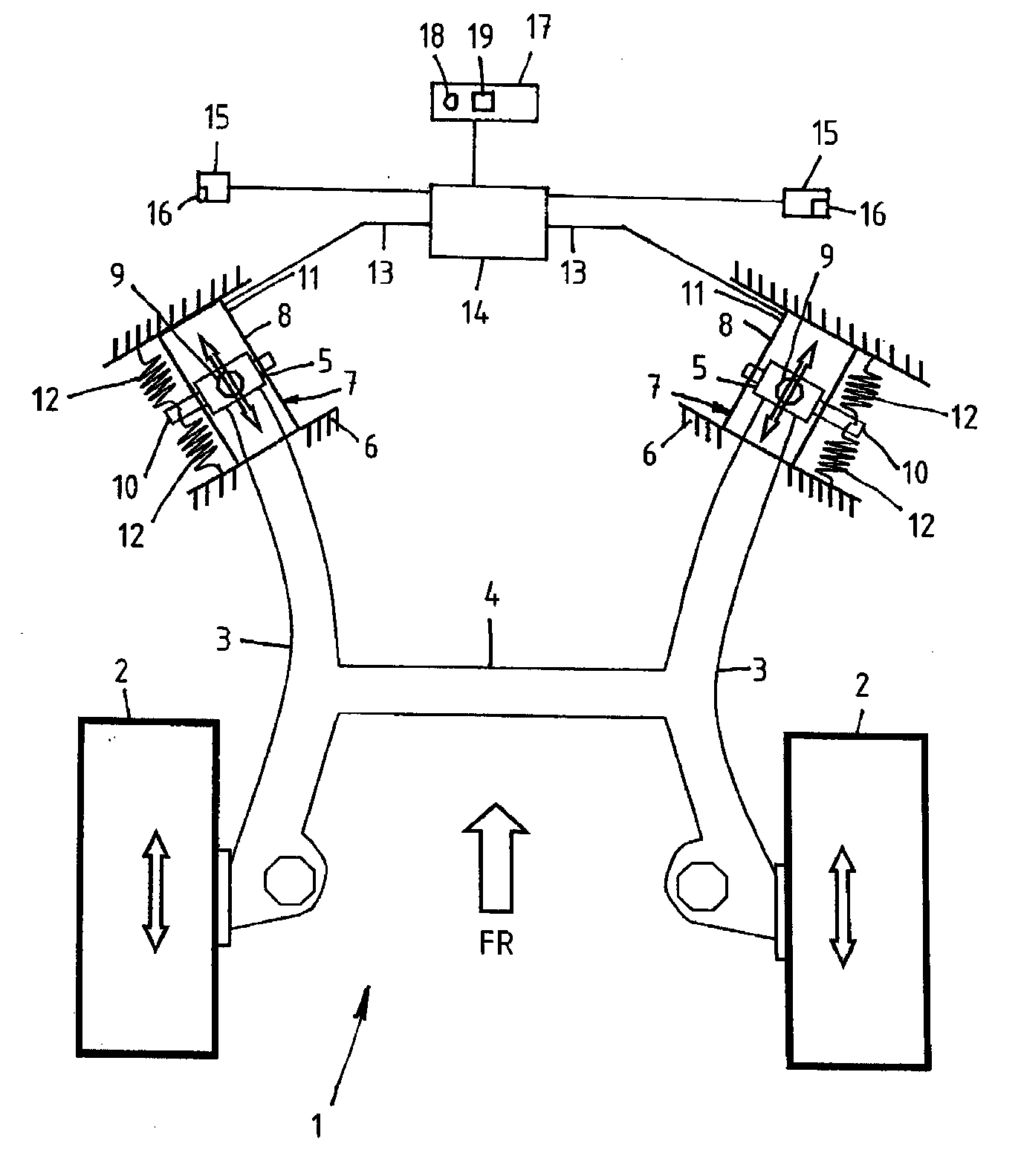
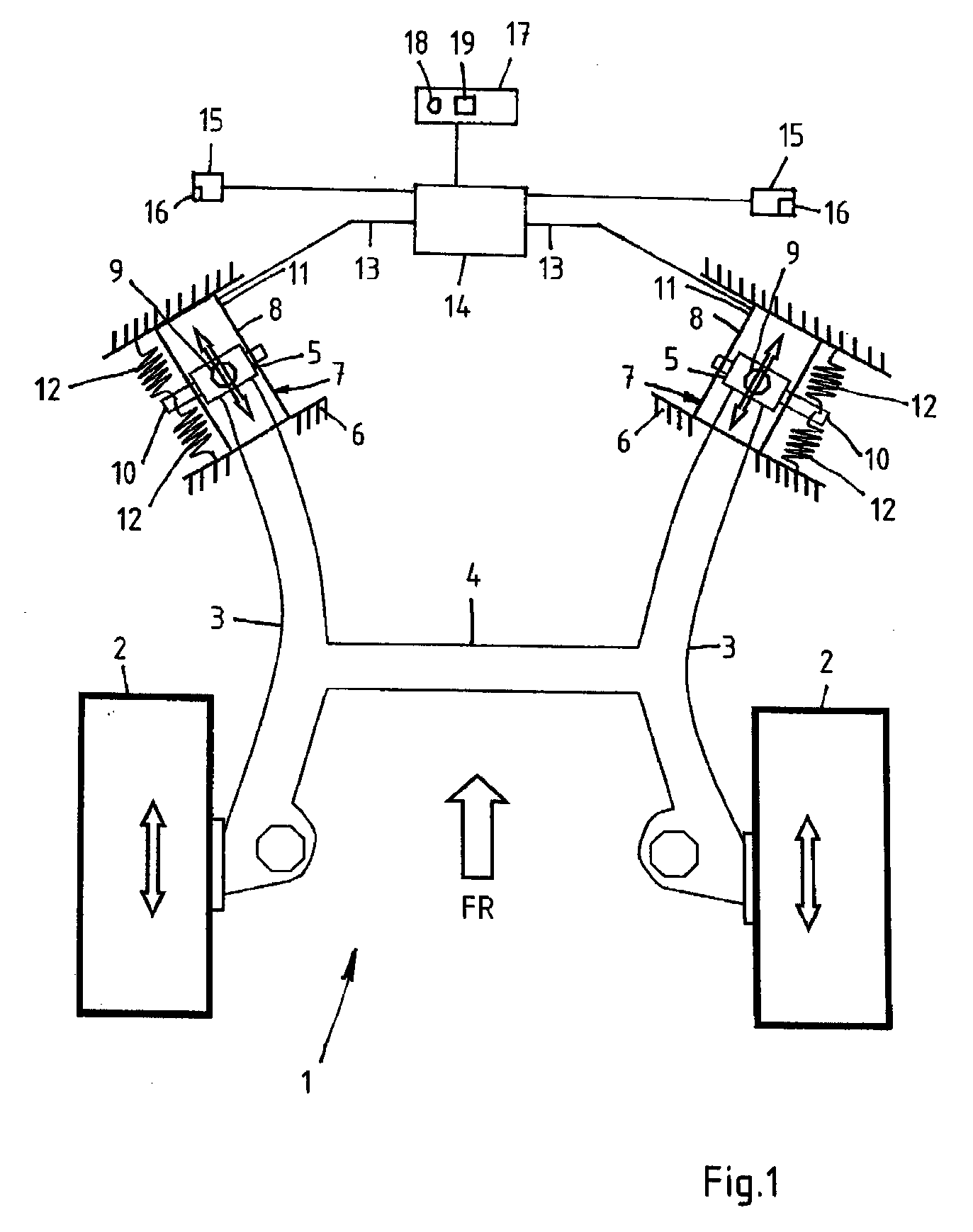
[0028] Turning now to the drawing, and in particular to FIG. 1, there is shown a top view of a wheel guidance according to the present invention, generally designated by reference numeral 1 and constructed as twist beam axle. The wheel guidance 1 provides guidance of wheels 2 which are caused to vibrate when traveling on a road surface. The travel direction is indicated by arrow FR. The wheel guidance 1 includes two trailing arms 3 and a wishbone 4. The trailing arms 3 are mounted to a vehicle body 6 by means of two bearings 5. Each bearing 5 is operatively connected to an active arrangement, generally designated by reference numeral 7, for chassis manipulation and oscillation damping. The active arrangements 7 include electromagnetic linear motors 8 having reactive parts 9, which are coupled to the anchor pins 10 of the bearings 5, and primary parts 11, which are coupled to the vehicle body 6. Further provided at each bearing 5 are two coil springs 12 which are placed in parallel r...

second embodiment

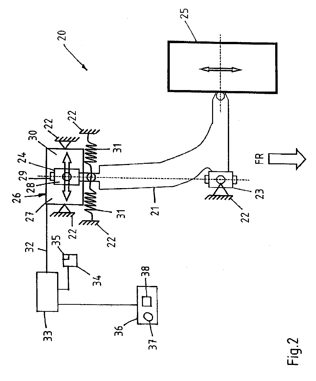
[0031] Referring now to FIG. 2, there is shown a top view of a wheel guidance according to the present invention, generally designated by reference numeral 20 and designed as McPherson axle. A wishbone 21 is connected to a vehicle body 22 via a supporting joint 23 and a guiding joint 24 for guiding a wheel 25. The travel direction is indicated by arrow FR, with the supporting joint 23 having a length axis pointing in travel direction FR. The wheel 25 is caused to vibrate when driving on a road surface. Operatively connected to the guiding joint 24 is an active arrangement, generally designated by reference numeral 26, for chassis manipulation and oscillation damping. The active arrangement 26 has an electromagnetic linear motor 27 which includes a reactive part 28 coupled to the guiding joint 24, and a primary part 30. The guiding joint 24 is hereby placed upon a pin 29 of the wishbone 21. The primary part 30 of the linear motor 27 is secured to the vehicle body 22. The longitudinal...


PUM


Abstract

A wheel guidance includes at least one bearing for articulation of a trailing arm or wishbone to a vehicle body. Oscillations caused during travel are detected by a sensor and superimposed by a compensation oscillation generated by a controller in combination with linear motors to provide oscillation damping.

Description

CROSS-REFERENCES TO RELATED APPLICATIONS [0001] This application claims the priority of German Patent Application, Serial No. 10 2005 026 047.0, filed Jun. 3, 2005, pursuant to 35 U.S.C. 119(a)-(d), the content of which is incorporated herein by reference. BACKGROUND OF THE INVENTION [0002] The present invention relates, in general, to a wheel guidance. [0003] Nothing in the following discussion of the state of the art is to be construed as an admission of prior art. [0004] Increasingly, consumers demand from a wheel guidance to provide more riding comfort, less oscillation buildup, less noise development and longer service life. A wheel guidance may be constructed as independent wheel suspension or in the form of twist-beam axle or rigid axle. Typical components of a wheel guidance include guide rods and bearings. The guide rods provide wheel guidance and are connected via bearings to the vehicle body as well as wheel carrier. Bearings are differentiated between supporting joints a...

Claims


Application Information

Patent Timeline
Patent Type & Authority Applications(United States)
IPC IPC(8): B60G7/00B60G17/056B60G11/18
CPCB60G7/006B62D17/00B60G17/0162B60G21/052B60G2200/132B60G2200/21B60G2200/462B60G2202/422B60G2202/424B60G2204/1434B60G2204/41B60G2204/4106B60G2400/104B60G2400/106B60G17/0157
Inventor ZUBER, ARMIN
Owner BENTELER AUTOMOBILTECHNIK GMBH
Learn More