
Method of and system for 3D display of multi-energy computed tomography images

a computed tomography and multi-energy technology, applied in tomography, instruments, applications, etc., can solve the problems of plastic explosives, baggage scanning systems may be particularly difficult to detect, plastic explosives may be formed into geometric shapes that are difficult to detect,

Inactive Publication Date: 2006-12-07
ANLOGIC CORP (US)
View PDF14 Cites 22 Cited by
  • Summary
  • Abstract
  • Description
  • Claims
  • Application Information

AI Technical Summary

Benefits of technology

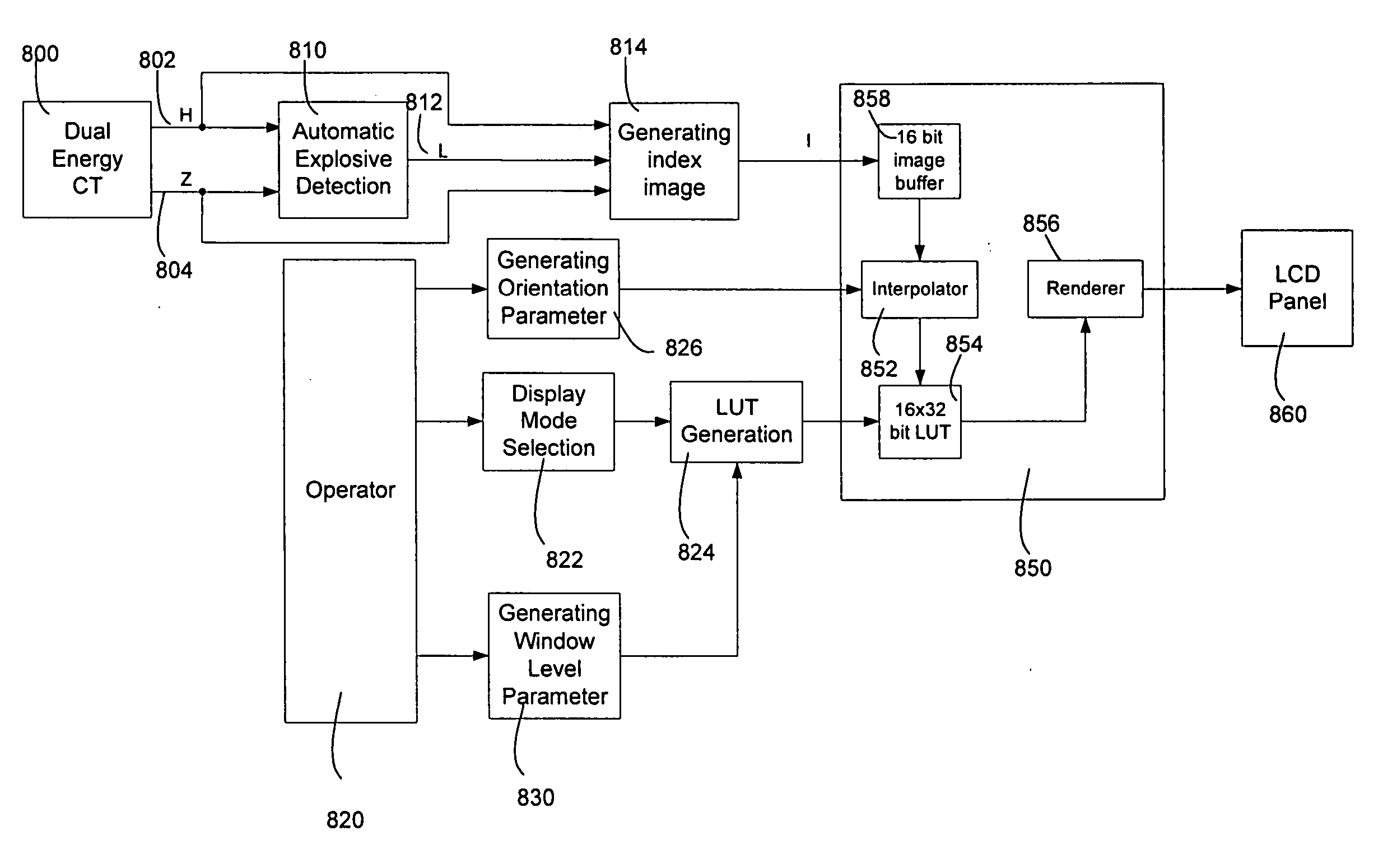
[0070] In accordance with one aspect of the disclosed method, volumetric multi-energy CT images, including a CT image, a Z image, and a label image are displayed from an automatic explosive detection, wherein the total number of bits of the CT image, the Z image, and the label image per voxel is N. The method comprises (a) generating an index image, of which each voxel has M bits, through a nonlinear transformation of the CT image, the Z image, and the label image, wherein M is less than N; (b) rotating and coloring the index image as desired; and (c) rendering and displaying the rotated and colored index image. In one embodiment, the coloring is performed after rotating the index image is performed. In one embodiment, coloring includes (a) generating an RGBA look-up-table corresponding to the selected display mode, and (b) applying the RGBA look-up-table to the rotated index image.

Problems solved by technology

Plastic explosives, however, present a particular challenge to baggage scanning systems.
Due to their moldable nature, plastic explosives may be formed into geometric shapes that are difficult to detect.
The detection of plastic explosives may be difficult because it may be difficult to see the explosive material in the image, particularly when the material is disposed so that the thin sheet is parallel to the direction of the X-ray beam as the sheet passes through the system.
Accordingly, a great deal of effort has been made to design a better baggage scanner.
The images from the post-reconstruction analysis usually do not yield accurate estimates of the material's effective atomic number, and suffer low SNR (Signal to Noise Ratio) and many artifacts as well.
The isotransmission line method requires a large amount of calibration data.
In such a situation, the linear equations are not valid and the method causes large approximation errors.
However, changing from one display mode to another is not necessarily easily and quickly accomplished.
Further, color rendering may make it difficult to see threat objects displayed within the scanned baggage, and therefore difficult to determine whether one is dealing with a false alarm, or a true threat.

Method used


Image

  • Method of and system for 3D display of multi-energy computed tomography images
  • Method of and system for 3D display of multi-energy computed tomography images
  • Method of and system for 3D display of multi-energy computed tomography images

Examples


Embodiment Construction

[0085] In accordance with at least one aspect of the present disclosure, a method and system are provided for displaying volumetric multi-energy CT images from the CT projection data acquired by scanning a set of objects using at least two x-ray spectra, wherein the projection data includes a set of low energy projections and a set of high energy projections. In one preferred embodiment, the method first generates a CT image and a Z (atomic number) image. An automatic explosive detection system generates a label image from the CT image and the Z image. A nonlinear transformation is then performed to transform the CT image, the Z image, and the label image into an index image for display, in which the number of bits per voxel is less than the total number of bits per voxel of the CT image, Z image, and label image. The index image is then loaded into the video memory of the display device once. Orientation angle for the luggage to be displayed on the screen input from an operator is ...


PUM


Abstract

A method of and a system for displaying volumetric multi-energy CT images are disclosed, wherein a CT image, a Z image, and a label image from an automatic explosive detection are provided, are disclosed. The method comprises generating an index image through a nonlinear transformation of the CT image, the Z image, and the label image, rotating and coloring the index image as desired, and rendering and displaying the rotated and colored image.

Description

RELATED APPLICATIONS [0001] This patent application and / or patents are related to the following co-pending U.S. applications and / or issued U.S. patents, of the assignee as the present application, the contents of which are incorporated herein in their entirety by reference: [0002]“Nutating Slice CT Image Reconstruction Apparatus and Method,” invented by Gregory L. Larson, et al., U.S. application Ser. No. 08 / 831,558, filed on Apr. 9, 1997, now U.S. Pat. No. 5,802,134, issued on Sep. 1, 1998; [0003]“Computed Tomography Scanner Drive System and Bearing,” invented by Andrew P. Tybinkowski, et al., U.S. application Ser. No. 08 / 948,930, filed on Oct. 10, 1997, now U.S. Pat. No. 5,982,844, issued on Nov. 9, 1999; [0004]“Air Calibration Scan for Computed Tomography Scanner with Obstructing Objects,” invented by David A. Schafer, et al., U.S. application Ser. No. 08 / 948,937, filed on Oct. 10, 1997, now U.S. Pat. No. 5,949,842, issued on Sep. 7, 1999; [0005]“Computed Tomography Scanning Appa...

Claims


Application Information

Patent Timeline
Patent Type & Authority Applications(United States)
IPC IPC(8): G06T17/00
CPCA61B6/03A61B6/482G06T11/008G01V5/005G01V5/0041G01V5/224G01V5/226
Inventor YING, ZHENGRONGHIRSCH, MATTHEWDESAI, PURVINGUILBERT, KYLESIMANOVSKY, SERGEYCRAWFORD, CARL R.
Owner ANLOGIC CORP (US)
Learn More