Measuring overlay and profile asymmetry using symmetric and anti-symmetric scatterometry signals

a scatterometry signal and overlay technology, applied in the field of scatterometry, can solve the problems of difficult to accurately model complicated profiles, rely on detailed modeling, and the cd-sem approach is very slow and expensiv

Active Publication Date: 2006-12-07
KLA TENCOR TECH CORP
View PDF5 Cites 45 Cited by
  • Summary
  • Abstract
  • Description
  • Claims
  • Application Information

AI Technical Summary

Benefits of technology

[0007] Systems and methods are disclosed for using the signals produced by an ellipsometer to determine the overlay error between two layer structures on a specimen, such as a semiconductor wafer, while accounting for any asymmetries in the produced signals. In one embodiment two or more signals, which do not necessarily satisfy any symmetry assumptions individually, are combined into a composite signal which satisfies a symmetry assumption. The individual signals are collected at two or more analyzer angles. Symmetry properties of the composite signals allow easy extraction of overlay information for any relative orientation of the incident light beam with

Problems solved by technology

The CD-SEM approach is very slow and expensive.
The current implementation of scatterometry CD metrology, which is also suitable for monitoring properties of the profile (including profile asymmetry), relies on detai

Method used


Image

  • Measuring overlay and profile asymmetry using symmetric and anti-symmetric scatterometry signals
  • Measuring overlay and profile asymmetry using symmetric and anti-symmetric scatterometry signals
  • Measuring overlay and profile asymmetry using symmetric and anti-symmetric scatterometry signals

Examples


Embodiment Construction

[0018] Reference will now be made in detail to a particular embodiment of the invention, examples of which are illustrated in the accompanying drawings. While the invention will be described in conjunction with the particular embodiments, it will be understood that it is not intended to limit the invention to the described embodiments. To the contrary, it is intended to cover alternatives, modifications, and equivalents as may be included within the spirit and scope of the invention as defined by the appended claims.

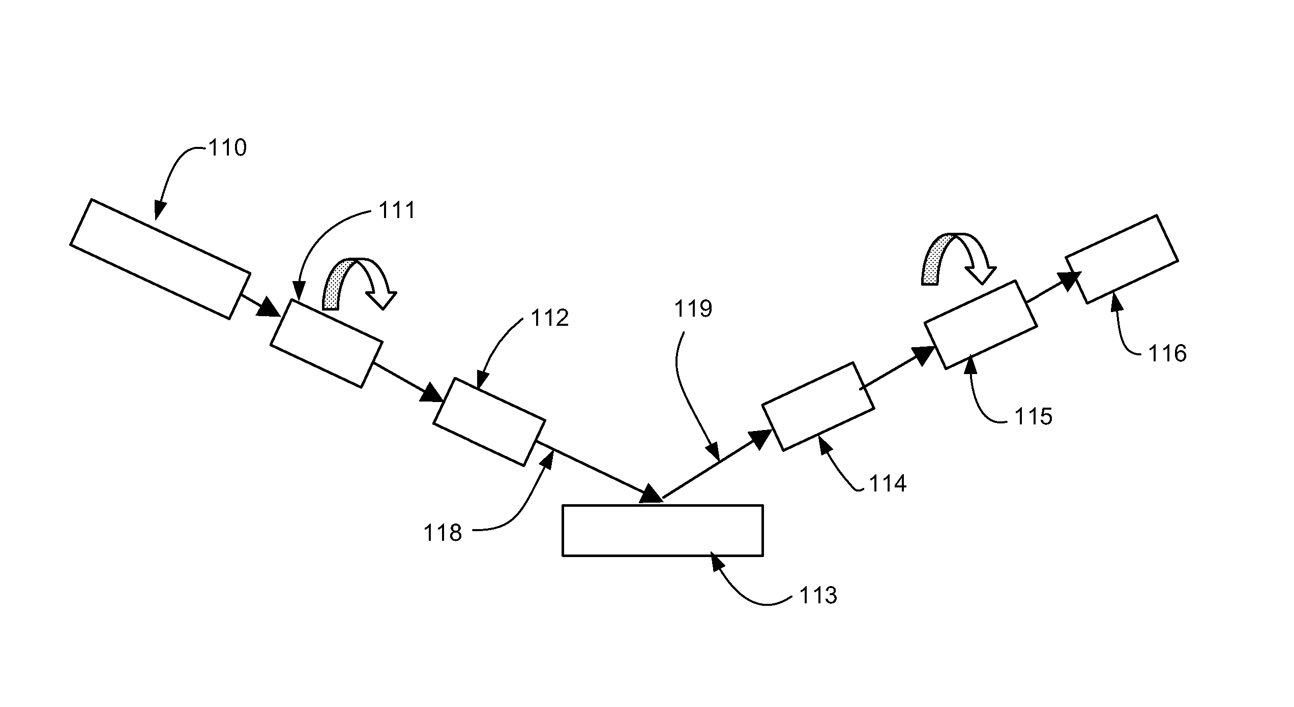
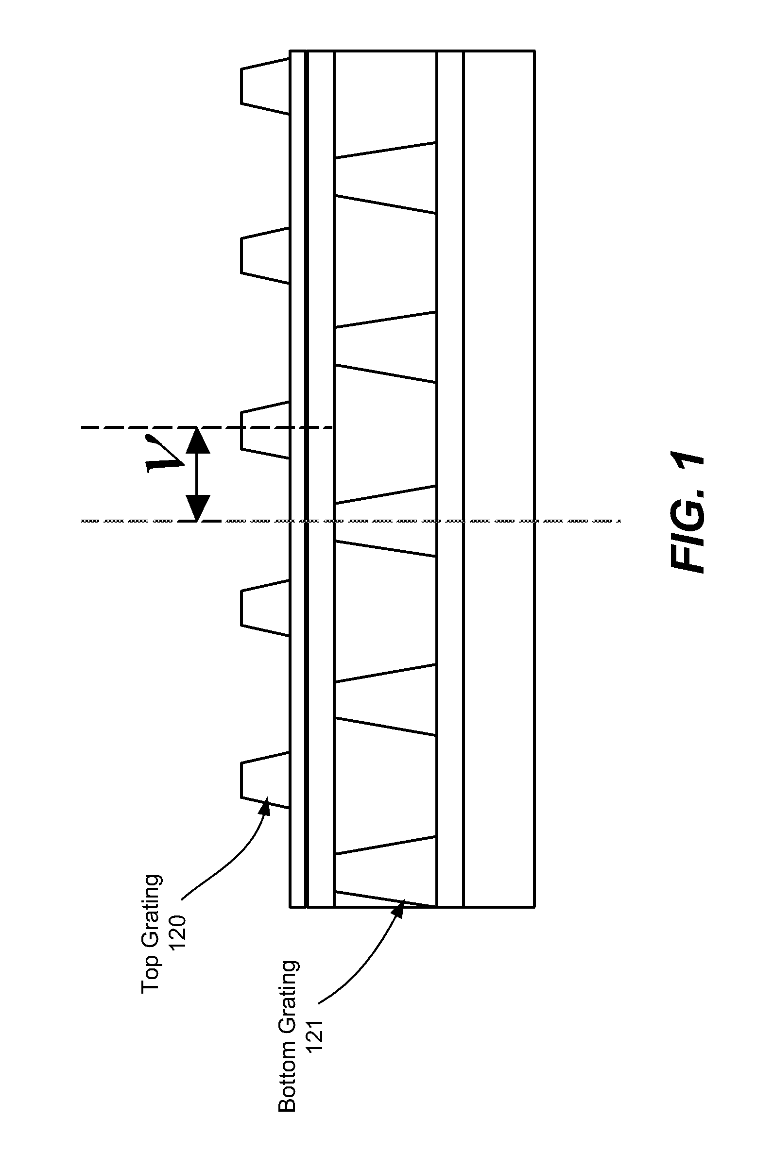
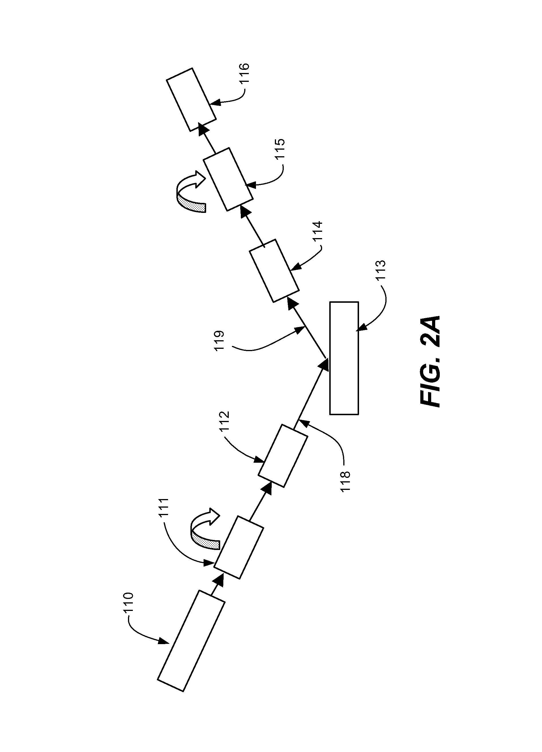
[0019] The present invention introduces a system and method for combining information from one or more ellipsometry signals in a manner which allows easy extraction of overlay information for any relative orientation of the incident light beam with respect to a 1D grating target, as well as for targets comprising general 2D gratings. In addition, the disclosed analysis of the ellipsometry signal yields qualitative information about the profile of the grating. The degree...


PUM


Abstract

Systems and methods are disclosed for using ellipsometer configurations to measure the partial Mueller matrix and the complete Jones matrix of a system that may be isotropic or anisotropic. In one embodiment two or more signals, which do not necessarily satisfy any symmetry assumptions individually, are combined into a composite signal which satisfies a symmetry assumption. The individual signals are collected at two or more analyzer angles. Symmetry properties of the composite signals allow easy extraction of overlay information for any relative orientation of the incident light beam with respect to a ID grating target, as well as for targets comprising general 2D gratings. Signals of a certain symmetry property also allow measurement of profile asymmetry in a very efficient manner. In another embodiment a measurement methodology is defined to measure only signals which satisfy a symmetry assumption. An optional embodiment comprises a single polarization element serving as polarizer and analyzer. Another optional embodiment uses an analyzing prism to simultaneously collect two polarization components of reflected light.

Description

CROSS REFERENCE TO RELATED PATENT APPLICATION [0001] This application claims priority of U.S. Provisional Patent Application No. 60 / 687,951 (Attorney Docket No. KLA1P148P) filed 6 Jun. 2005 by Daniel Kandel et al., which application is incorporated herein by reference in its entirety for all purposes.FIELD OF INVENTION [0002] The invention pertains in general to scatterometry, and in particular to measuring overlay error and profile asymmetry using symmetric and anti-symmetric scatterometry signals. BACKGROUND OF THE INVENTION [0003] Scatterometry is currently used in the semiconductor industry to measure thickness and optical properties of thin films as well as the critical dimension (CD) and profile shape of periodic structures on a semiconductor wafer. Scatterometry is also perceived as a possible future technology for overlay error metrology for the 32 nm technology node and beyond. In principle, scatterometry has clear advantages over the current imaging technology of overlay m...

Claims


Application Information

Patent Timeline
IPC IPC(8): G01J4/00
CPCG01N21/211G03F7/70633G01N21/956G01N21/9501G01J4/00
Inventor KANDEL, DANIELGROSS, KENNETH P.FRIEDMANN, MICHAELFU, JIYOUKRISHNAN, SHANKARGOLOVANEVSKY, BORIS
Owner KLA TENCOR TECH CORP
Why Eureka
Try Eureka