Light module

a technology of light modules and encapsulating materials, applied in semiconductor devices for light sources, semiconductor/solid-state device details, lighting and heating apparatus, etc., can solve the problems of reducing the reliability of products, encapsulating material layers breaking in half or detaching from the substrate, and increasing the stress level of the overall package structure. , to achieve the effect of fast heat dissipation

Active Publication Date: 2006-12-07
LEXTAR ELECTRONICS CORP
View PDF4 Cites 45 Cited by
  • Summary
  • Abstract
  • Description
  • Claims
  • Application Information

AI Technical Summary

Benefits of technology

[0012] Since a fluid material with a free-flow ability is used in the light module according to the present invention, the heat generated by the light-emitting elements, such as diode chips or diode package bodies, can be easily dissipated by means of fluid flow (convection). Therefore, in addition to the heat dissipation path beneath the light-emitting elements as that used in a conventional structure, a heat dissipation path above the light-emitting elements is further constructed in the LED module according to the present invention. Accordingly, heat dissipation is fast and yellowing of the packaging or encapsulating material is retarded.

Problems solved by technology

Hence, it is disadvantageous that as the encapsulating material layer gets more rigid, the stress level of the overall package structure will increase accordingly, which will easily cause the encapsulating material layer to break in half or detach from the substrate and decrease the reliability of the product.
Furthermore, the conventional encapsulating material layer has poor heat dissipation ability and a poor UV resistance, and thus a yellowing is likely to occur.
In case that the entire LED module is formed by aggregating a plurality of LED package bodies on the substrate, the volume of the resulted LED module will be relatively large and heat dissipation is still poor, resulting a short life time.
The encapsulating material still has disadvantages of tending to be yellowing and having low heat dissipation properties.

Method used


Image

  • Light module
  • Light module
  • Light module

Examples


Embodiment Construction

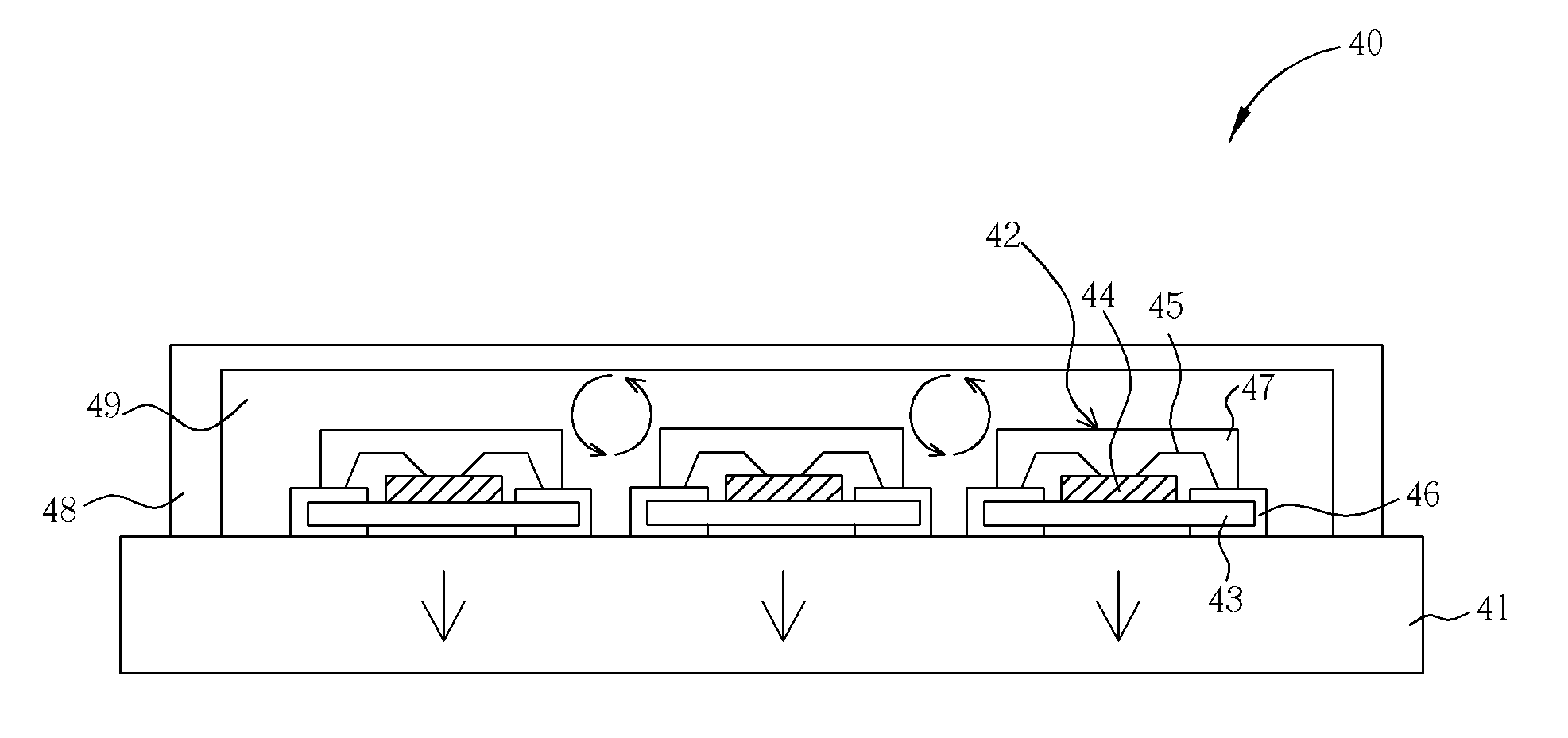
[0018] Please refer to FIGS. 3 and 4. FIGS. 3 and 4 are each a schematic cross-sectional diagram showing an LED module of an embodiment according to the present invention, respectively. The light emitting elements suitably used in the light modules are not limited to a particular type. Herein, the light module including LED chips or LED package bodies as light-emitting elements is described for illustration. As shown in FIG. 3, the light module 30 according to the present invention comprises a substrate 31, at least one LED chip 32 as a light-emitting element, a sealing cap 34, and a fluid 35.

[0019] The substrate 31 may be a heat transferring plate with heat conductivity or further with electric conductivity. One or more LED chips 32 are disposed on the substrate 31 and electrically connected with, for example, conductive wires 33. A plurality of LED chips for emitting a single color light may be used to increase light intensity. Also, a plurality of LED chips for emitting differen...


PUM


Abstract

Disclosed herein is a light module comprising a substrate, at least one light-emitting element on the substrate, a sealing cap on the substrate and covering the light-emitting elements, and a fluid in the space formed among the sealing cap, the light-emitting elements, and the substrate, such that heat dissipation is fast and yellowing of the encapsulating material is retarded.

Description

BACKGROUND OF INVENTION [0001] 1. Field of the Invention [0002] The present invention relates to a light module, and more particularly to a high-power light module packaged with both solid and fluid packaging materials. [0003] 2. Description of the Prior Art [0004] A cold illumination LED has the advantages of low power consumption, long device lifetime, no idling time, and quick response speed. In addition, since the LED also has the advantages of small size, suitability for mass production, and ease of fabrication as a tiny device or an array device, it has been widely applied in display apparatus and indicating lamps used in information, communication, consumer electronic products, and automotive industry, such as, cellular phones, as backlights of personal data assistants, outdoor traffic signal lamps or various outdoor displays, even as a components in the highly popular liquid crystal displays. [0005]FIGS. 1 and 2 are each a cross section diagram showing a conventional LED mod...

Claims


Application Information

Patent Timeline
Patent Type & Authority Applications(United States)
IPC IPC(8): F21V9/00
CPCF21K9/00H01L25/0753H01L2224/48247H01L33/648H01L33/50H01L2924/181H01L2924/00012
Inventor CHANG, CHIH-CHINHUANG, TENG-HUEILEE, CHIEN-LUNG
Owner LEXTAR ELECTRONICS CORP
Why Eureka
Try Eureka