Waveform shaping method, waveform shaping device, electronic device, waveform shaping program and recording medium

a waveform shaping and waveform technology, applied in the field of waveform shaping methods, waveform shaping devices, electronic devices, waveform shaping programs and recording media, can solve problems such as system failure and system malfunction of wireless video transfer systems

Inactive Publication Date: 2006-12-07
SHARP KK
View PDF6 Cites 16 Cited by
  • Summary
  • Abstract
  • Description
  • Claims
  • Application Information

AI Technical Summary

Benefits of technology

[0045] The function and effect of lengthening the pulse interval are explained in a description regarding a method of carrying out waveform shaping, in which, when a no-pulse period is less than a setting value, a no-pulse period is used as a setting value.
[0046] Note that the ...

Problems solved by technology

As a result, the wireless video transfer sys...

Method used


Image

  • Waveform shaping method, waveform shaping device, electronic device, waveform shaping program and recording medium
  • Waveform shaping method, waveform shaping device, electronic device, waveform shaping program and recording medium
  • Waveform shaping method, waveform shaping device, electronic device, waveform shaping program and recording medium

Examples


embodiment 1

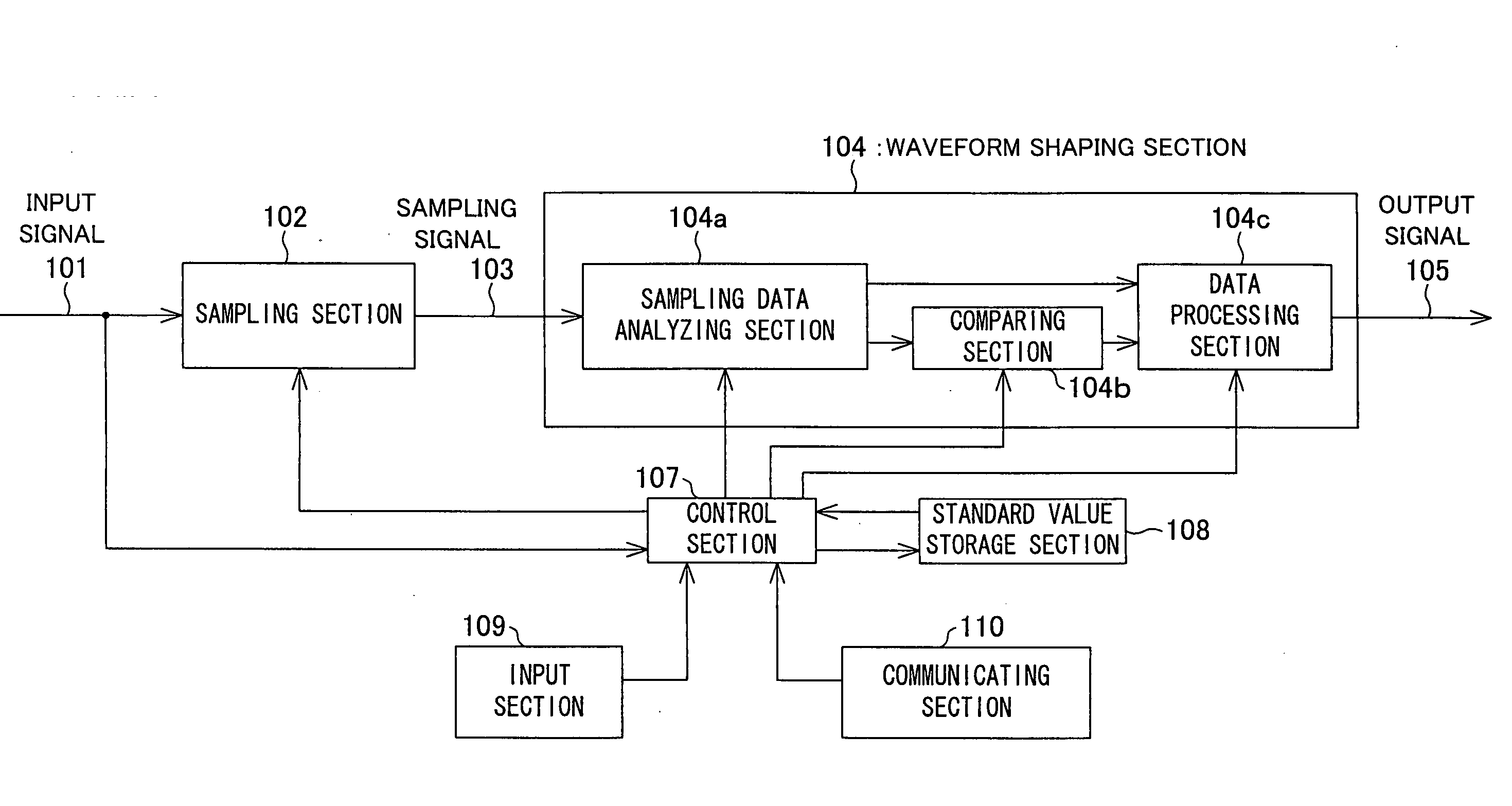
[0089] A waveform shaping method and a waveform shaping device of the present invention realize a structure for properly reproducing, on a wireless station side, a digital signal such as a remote-control signal whose information is subjected to a wireless transmission. Such a structure is realized by an arrangement in which: (i) a conventional sampling section 302 of a television 207 shown in FIG. 23 is improved so that the sampling section 302 corrects a distortion which has been generated by a conventional infrared receiving section 301; and (ii) the waveform shaping method and the waveform shaping device are made to be all-applicable method and device which are not influenced by a characteristic of the infrared receiving section 301.

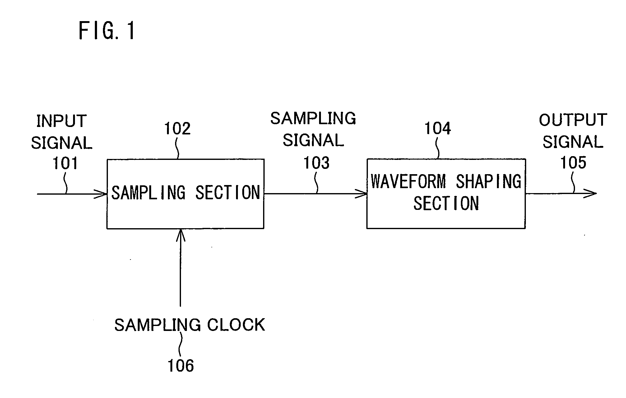
[0090] In the present invention, the sampling section 302 is replaced with an improved sampling section (sampling means) 102 and a waveform shaping section (waveform shaping means) 104 illustrated, as constituting a waveform shaping device of the pre...

embodiment 2

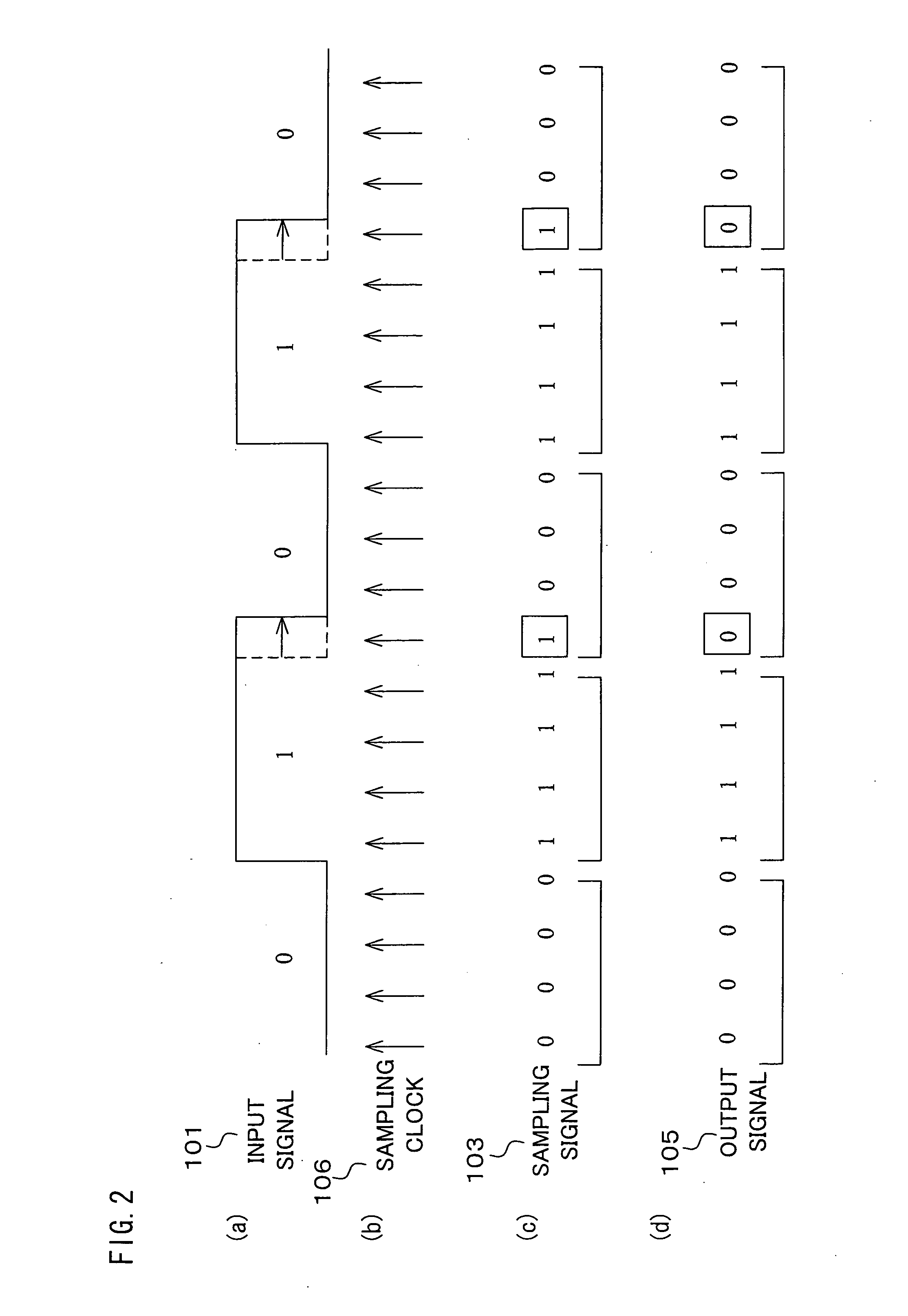
[0141] In general, a headmost portion of a pulse in a signal (an input signal 101 to be inputted to a sampling section 102) outputted from an infrared receiving section 301 is properly outputted. However, a portion on a rear side of the pulse tends to be lengthened. A waveform shaping may be carried out with respect to both rising and falling edges. However, in consideration of the characteristic, it is possible to be close to the original waveform, while an occurrence of jittering is restrained, by carrying out the waveform shaping with respect to the falling edge (See FIG. 2(a) to FIG. 2(d)), and not to the rising edge.

embodiment 3

[0142] In general, information is often transmitted by making a pulse width fixed in a remote control signal, as illustrated in FIG. 3(a), while varying a pulse interval. For example, a first interval is determined as data “0”, and a second interval which is longer than the first interval is determined as data “1”. When the remote-control signal is outputted from the infrared receiving section 301, the pulse width may be lengthened by various amounts, as illustrated in FIG. 3(b).

[0143] In this case, as illustrated in FIG. 3(c), a waveform of the pulse may be made close to an original pulse waveform, by carrying out the waveform shaping with respect to any pulse containing a distortion so that the pulse widths of all the pulses are made to be close to predetermined pulse widths.

[0144] Incidentally, at the time of carrying out a communication, the pulse width is previously determined in many cases. For example, according to remote-control symbols of a company A (i) a pulse width is ...


PUM


Abstract

A sampling section (102) is provided for generating a sampling signal (103) by sampling an input signal (101) using a sampling clock (106) which is faster than a data speed of the input signal (101). A waveform shaping section (104) is provided for I) processing (e.g. inverting a pulse) the sampling signal (103), so as to shape a restored digital signal obtained from a pulse of the input signal (101), and II) outputting the restored digital signal as an output signal (105). In this way, it becomes possible to provide: A) a waveform shaping method and a waveform shaping device, each of which is capable of correcting distortion in an input signal by means of a simple method or configuration; B) a waveform shaping program that realizes the waveform shaping method or the waveform shaping device; and C) a recording medium storing therein the waveform shaping program.

Description

TECHNICAL FIELD [0001] The present invention relates to a waveform shaping method, a waveform shaping device, and an electronic device for (i) appropriately restoring and reproducing an original digital signal or (ii) acquiring an appropriate process result as is acquired by directly processing the original signal, despite a distortion in a waveform of a pulse train constituting the original signal. The present invention also relates to a waveform shaping program for realizing, in a computer, a function of the waveform shaping method, the waveform shaping device, or the electronic device, and relates to a recording medium storing therein such a waveform shaping program. BACKGROUND ART [0002] In general, a remote control (remote controlling device) is used for remotely controlling a television, a video player or the like. Meanwhile, various businesses are engaged in producing a wireless television. For example, Toshiba corp. has placed wireless televisions on the market having model ...

Claims


Application Information

Patent Timeline
IPC IPC(8): H04L7/00H03K5/05G11B20/10H03K5/04H03K5/1252H03K17/00H04L25/02H04L25/03H04Q9/00
CPCG11B20/10009G11B20/10037H04L25/03834H03K5/04G11B20/10046
Inventor IKEDA, YUTAKAARAMAKI, TAKASHI
Owner SHARP KK
Why Eureka
Try Eureka