Fuser having reduced axial temperature droop
- Summary
- Abstract
- Description
- Claims
- Application Information
AI Technical Summary
Benefits of technology
Problems solved by technology
Method used
Image
Examples
example 1
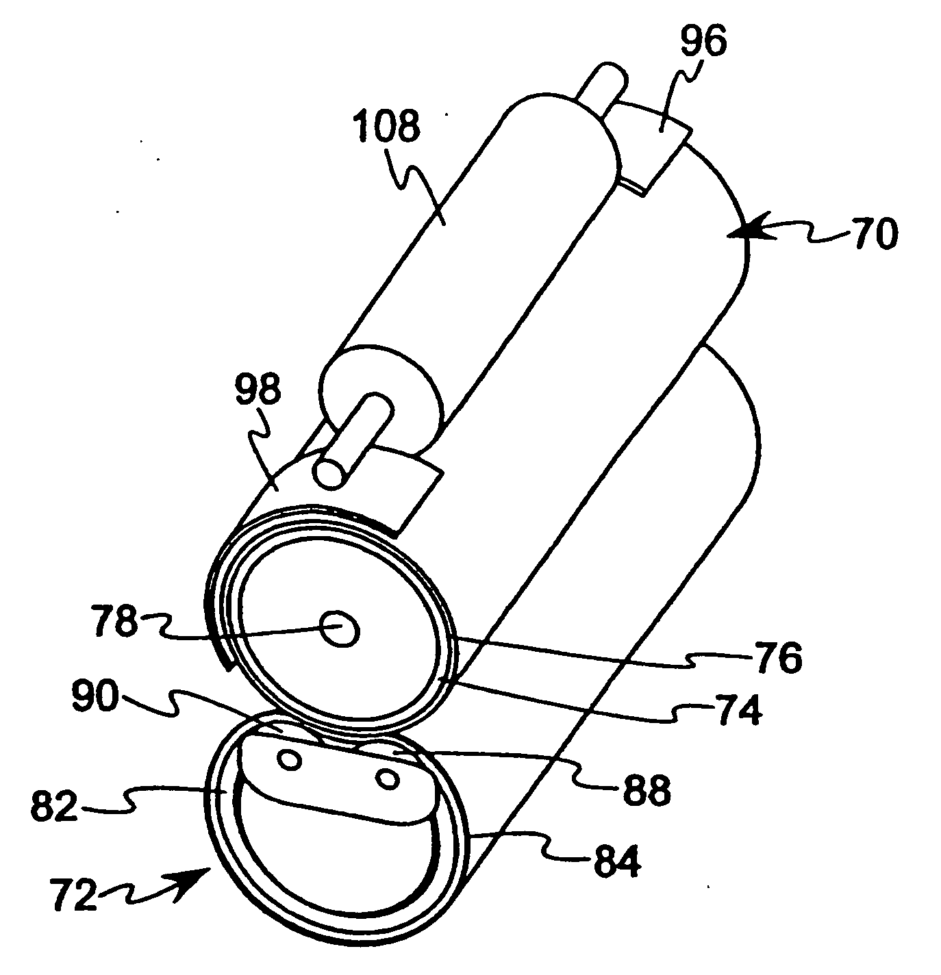
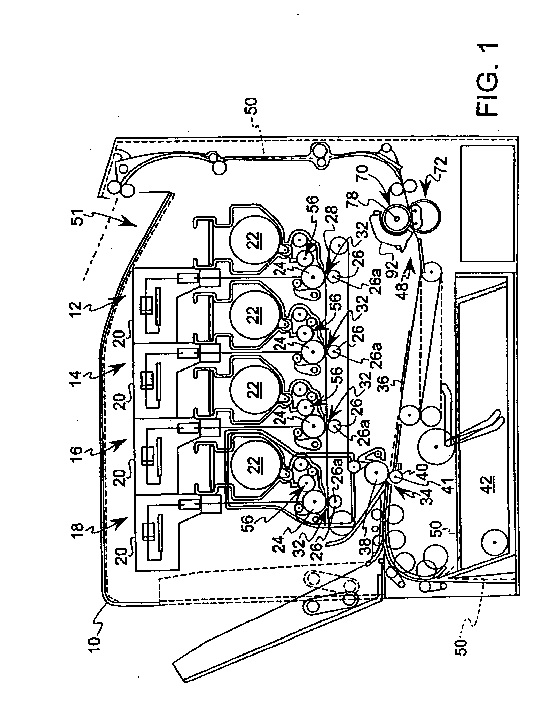
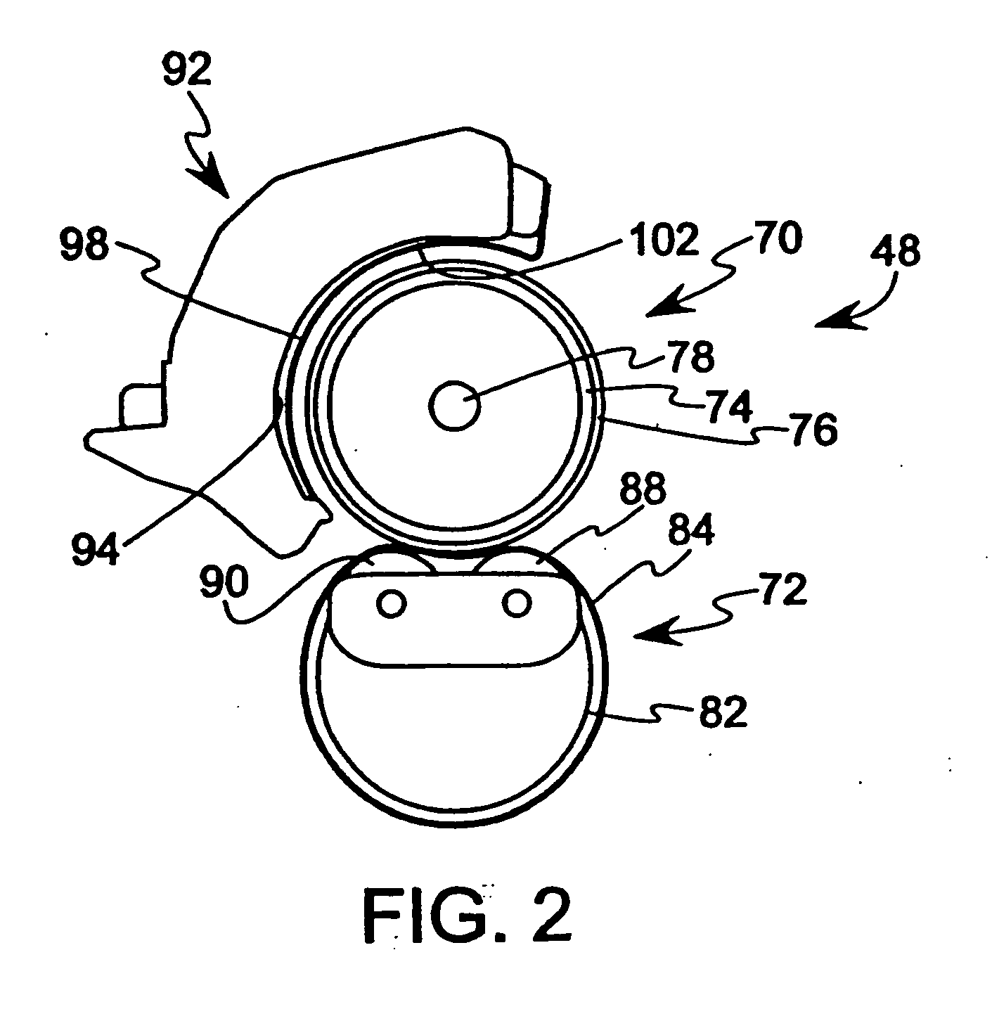
[0043] A fuser was provided including a hot roller 70 having a steel core 74 formed with an outer diameter of approximately 24.8 mm and a thickness of approximately 0.4-0.5 mm, a silicone rubber layer 76 provided over the steel core having a thickness of approximately 0.5-0.6 mm, and a PFA layer provided over the silicone rubber layer 76 having a thickness of approximately 40 microns. The length of the hot roller 70 was approximately 246 mm. The hot roller 70 was engaged with a backup member, such as the backup member 72 described above with reference to FIG. 2, to define a fixing nip between the hot roller 70 and the backup member 72. A 650 W halogen lamp 78 was located in the steel core 74, extending along the central longitudinal axis of the hot roller 70, and including a filament boosted by approximately 10% at each of the opposing ends.
[0044] Side reflectors 96, 98 were provided adjacent to the circumferential surface of the hot roller 70 adjacent each end of the hot roller 70...
example 2
[0046] In an alternative embodiment of a fuser, a hot roller 70 and backup member 72 as described for Example 1 was provided. Side reflectors 96, 98 were provided adjacent to each end of the hot roller 70, including a gear side reflector 96 having a width of approximately 50 mm extending approximately 129° around the hot roller 70, and a non-gear side reflector 98 having a width of approximately 45 mm extending approximately 129° around the hot roller 70. The side reflectors 96, 98 were supported on an inner side 94 of a fuser cover 92 facing toward the hot roller 70. The fuser cover 92 comprised a solid cover without ventilation windows.
[0047] A steel heat absorbing roller 108, as described with reference to FIG. 4, was positioned between the side reflectors 96, 98, where the heat absorbing roller 108 was in engagement with the outer surface of the hot roller 70 during steady state operation in a standby mode in which the hot roller 70 and belt 84 were stationary. The heat absorbi...
example 3
[0049] In a third embodiment of a fuser, a hot roller 70 and backup member 72 as described for Example 1 was provided. Side reflectors 96, 98 were provided adjacent to each end of the hot roller 70, including a gear side reflector 96 having a width of approximately 50 mm extending approximately 129° around the hot roller 70, and a non-gear side reflector 98 having a width of approximately 45 mm extending approximately 129° around the hot roller 70. The side reflectors 96, 98 were supported on an inner side 94 of a fuser cover 92′ facing toward the hot roller 70. In addition, the fuser cover 92′ included ventilation windows 110 for permitting air to pass through the cover 92′, as described with reference to FIG. 5. Specifically, a plurality of ventilation windows 110 were provided in at least a portion of the cover 92′ extending from the gear side reflector 96 toward the non-gear side reflector 98, where a portion of the cover 92′ adjacent the non-gear side reflector 98 was not provi...
PUM
 Abstract
Description
Claims
Application Information
 - R&D
- Intellectual Property
- Life Sciences
- Materials
- Tech Scout
- Unparalleled Data Quality
- Higher Quality Content
- 60% Fewer Hallucinations
Browse by: Latest US Patents, China's latest patents, Technical Efficacy Thesaurus, Application Domain, Technology Topic, Popular Technical Reports.
© 2025 PatSnap. All rights reserved.Legal|Privacy policy|Modern Slavery Act Transparency Statement|Sitemap|About US| Contact US: help@patsnap.com


