
Method for producing birefringent film, optical film and image display device using the same

a technology of optical film and image display device, which is applied in the direction of manufacturing tools, polarising elements, instruments, etc., can solve the problems of inability to achieve sufficient relaxing effect, difficulty in achieving uniform alignment axis, and inconvenient operation, etc., to achieve excellent optical characteristics, efficient operation, and excellent appearance

Inactive Publication Date: 2006-12-07
NITTO DENKO CORP
View PDF31 Cites 18 Cited by
  • Summary
  • Abstract
  • Description
  • Claims
  • Application Information

AI Technical Summary

Benefits of technology

[0013] By causing the polymer film to be stretched in the width direction while being shrunk in the longitudinal direction and setting the degree of stretching in the width direction and the degree of shrinking in the longitudinal direction so as to satisfy the requirement represented by the formula (1) as described above, it is possible to efficiently obtain a birefringent film that has excellent appearance and also excellent optical characteristics with refractive indices in the in-plane direction and the thickness direction being controlled precisely and a birefringence, a retardation and an alignment axis, especially an alignment axis accuracy in the width direction, being uniform. A birefringent film obtained by such a production method can improve, for example, display characteristics of various image displays such as a liquid crystal display due to its properties. Besides, the birefringent film can be attached to a polarizing film continuously as described above. Hence, the birefringent film is very useful from an industrial viewpoint.
[0014] Note here that an idea of causing the polymer film to be stretched in the width direction while being shrunk in the longitudinal direction and setting a condition for performing the stretching and shrinking so as to satisfy the formula (1) as described above is newly discovered by the inventors of the present invention through in-depth research. More specifically, the inventors of the present invention compared deformation of a polymer film caused by conventional stretching in the width direction and deformation of a polymer film caused by conventional stretching in the longitudinal direction, and focused on the fact that these deformations exhibited the behavior as shown in Table 1 below. Table 1 shows change ratios of a polymer film in three dimensions (i.e., the longitudinal direction, the width direction, and the thickness direction). In Table 1, the change ratios are represented as values obtained assuming that the width, the length, and the thickness of the polymer film before being stretched are “1”, and STD represents the change ratio in the width direction while SMD represents the change ratio in the longitudinal direction. That is, the inventors of the present invention focused on the fact that, as shown in Table 1, the conventional stretching in the width direction causes no deformation in the longitudinal direction, which may be one reason why the bowing phenomenon occurs, whereas, according to the conventional stretching in the longitudinal direction, it is generally easy to cause desired deformations in the width direction and the thickness direction. Based on this finding, the inventors conducted in-depth research, thereby arriving at the present invention. TABLE 1Deformation inDeformation inDeformation inlongitudinal directionwidth directionthickness directionPrior artStretching in1STD1 / STDwidthdirectionPrior artStretching inSMDSTD = (1 / SMD)1 / 2(1 / SMD)1 / 2longitudinaldirectionPresentStretching + Shrinking(1 / STD)1 / 2 ≦ SMDSTD(1 / SMD)1 / 2invention

Problems solved by technology

However, arranging the birefringent film and the polarizing film in the above-described manner involves the following problem in production.
Therefore, it is difficult to achieve uniformity in alignment axis, birefringence, and retardation by stretching the polymer film in the width direction.
However, since the polymer film generally is formed on a base directly and then is stretched together with the base, the method may be affected by variation in physical properties of the base.
Moreover, depending on the type of the polymer film, sufficient relaxing effect cannot be obtained.
Therefore, according to this method, it is difficult to produce uniform birefringent films stably by an industrial process.
Furthermore, although there has been an attempt to suppress the bowing phenomenon by cooling the polymer film after stretching, this cannot avoid the bowing phenomenon completely (e.g., Non-patent Document 1).
However, this method has problems that the base used is limited to a heat shrinkable base and that, if the base is too thick, wrinkles may be formed when loosening the base, thereby making it difficult to loosen the base stably.
However, from an industrial viewpoint, it is difficult to produce birefringent films stably according to these methods.

Method used


Image

  • Method for producing birefringent film, optical film and image display device using the same
  • Method for producing birefringent film, optical film and image display device using the same
  • Method for producing birefringent film, optical film and image display device using the same

Examples


example 1

[0101] Using a high-performance thin film machine (trade name: “FITZ”; manufactured by The Ichikin, Ltd.), an unstretched polycarbonate film (manufactured by Kaneka Corporation) having a thickness of 68 μm and a width of 330 mm continuously was stretched in the width direction while being shrunk in the longitudinal direction, thus forming a birefringent film. Note here that the above treatment was carried out at a temperature of 160° C. so that the STD in the width direction would be 1.2 and the SMD in the longitudinal direction would be 0.93. The value of (1 / STD)1 / 2 was 0.913, so that the requirement represented by the formula (1) above was satisfied. With regard to this birefringent film, variation in alignment axis angle in the width direction, in-plane retardation (Δnd=(nx−ny)·d) as well as variation therein, retardation (Rth=(nx−nz)·d) in the thickness direction as well as variation therein were measured in the above-described manner, and the occurrence of wrinkles and cracks w...

example 2

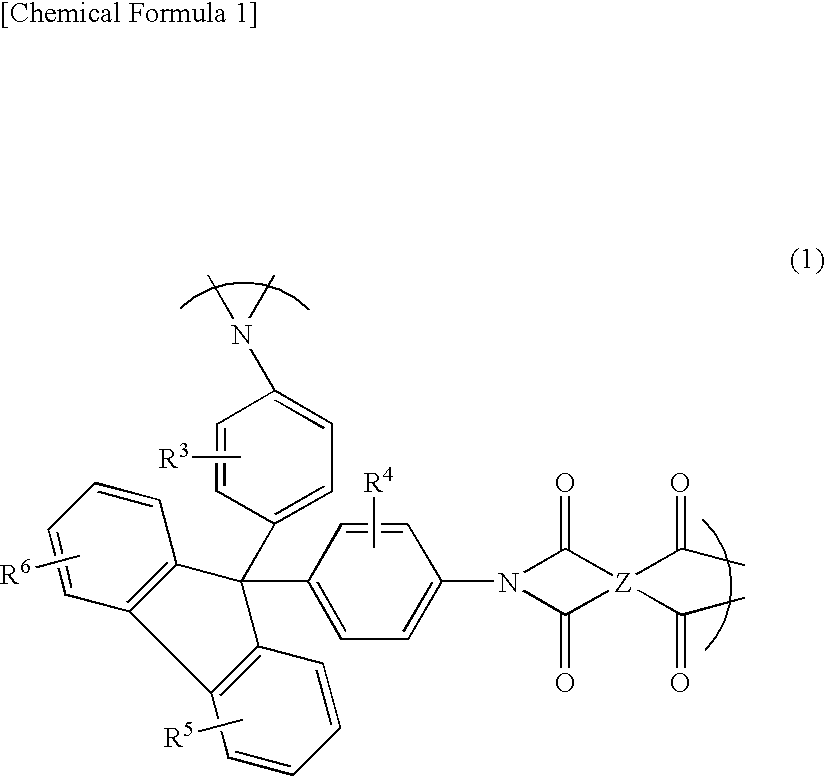
[0104] As a material for forming a polymer film, polyimide (Mw=120000) whose repeating unit was represented by the general formula (6) below was synthesized from 2,2′-bis(3,4-dicarboxyphenyl)hexafluoropropane dianhydride (6FDA) and 2,2′-bis(trifluoromethyl)-4,4′-diaminobiphenyl (PFMB). Then, this polyimide was dissolved in MIBK to prepare a 20 wt % polyimide solution. The thus-obtained polyimide solution was continuously coated on a TAC film (trade name: TF80UL; manufactured by Fuji Photo Film Co., Ltd.) (400 mm in width, 40 μm in thickness) by blade coating. The polyimide coating layer was dried at 120° C. for 2 minutes, thus forming a polyimide film having a thickness of 6.0 μm. This polyimide film had birefringence exhibiting optical uniaxiality (nx=ny>nz), an in-plane retardation of 0.4 nm, and a retardation in the thickness direction of 248 nm. Moreover, a laminate of the base and the polyimide film was continuously stretched in the width direction while being shrunk in the lon...


PUM

PropertyMeasurementUnit
light transmittanceaaaaaaaaaa
thicknessaaaaaaaaaa

Abstract

A birefringent film with excellent uniformity in in-plane retardation, retardation in the thickness direction, and alignment axis is provided. The birefringent film is produced in such a manner that, in the step of stretching a polymer film, the polymer film is stretched in a width direction while being shrunk in a longitudinal direction, and assuming that lengths in the width direction and the longitudinal direction of the polymer film before being stretched are 1, a change ratio (STD) of the length in the width direction of the polymer film resulting from the stretching and a change ratio (SMD) of the length in the longitudinal direction of the polymer film resulting from the shrinking satisfy the following formula (1). (1 / STD)1 / 2≦SMD<1   (1)

Description

TECHNICAL FIELD [0001] The present invention-relates to a method for producing a birefringent film, and also to an optical film and various image displays using the birefringent film. BACKGROUND ART [0002] In various image displays such as a liquid crystal display, a birefringent film generally is used for the purpose of, for example, solving coloring or widening a viewing angle, in order to improve display characteristics. In general, such a birefringent film is produced by stretching a polymer film uniaxially or biaxially so as to adjust the birefringence or retardation of the polymer film. [0003] In the case where such a birefringent film is used in a liquid crystal display together with a polarizing film, it is generally necessary to arrange the birefringent film and the polarizing film so that the slow axis of the birefringent film is parallel to the transmission axis of the polarizing film. In general, the direction of the slow axis of a birefringent film coincides with the fi...

Claims


Application Information

Patent Timeline
Patent Type & Authority Applications(United States)
IPC IPC(8): B29C55/08C09K19/00B29C55/02B29L11/00G02B5/30G02F1/1335G02F1/13363
CPCG02B5/3033Y10T428/1041G02B5/3083C09K2323/031B29C55/12B32B2307/42G02B5/3041G02F1/133528G02F1/13363
Inventor ISHIBASHI, KUNIAKITSUCHIMOTO, KAZUKIYOSHIMI, HIROYUKI
Owner NITTO DENKO CORP
Learn More