Color image forming method and color toner forming method

a color image and toner technology, applied in the field of color image forming method and color toner forming method, can solve the problems of large temperature difference between portions of large temperature difference between the roller contacting and not contacting the image transfer body, and image defects known as hot-offset, etc., to achieve stable high gloss, suppress excess thermal energy supply, and stable high gloss

Active Publication Date: 2006-12-07
FUJIFILM BUSINESS INNOVATION CORP
View PDF8 Cites 19 Cited by
  • Summary
  • Abstract
  • Description
  • Claims
  • Application Information

AI Technical Summary

Benefits of technology

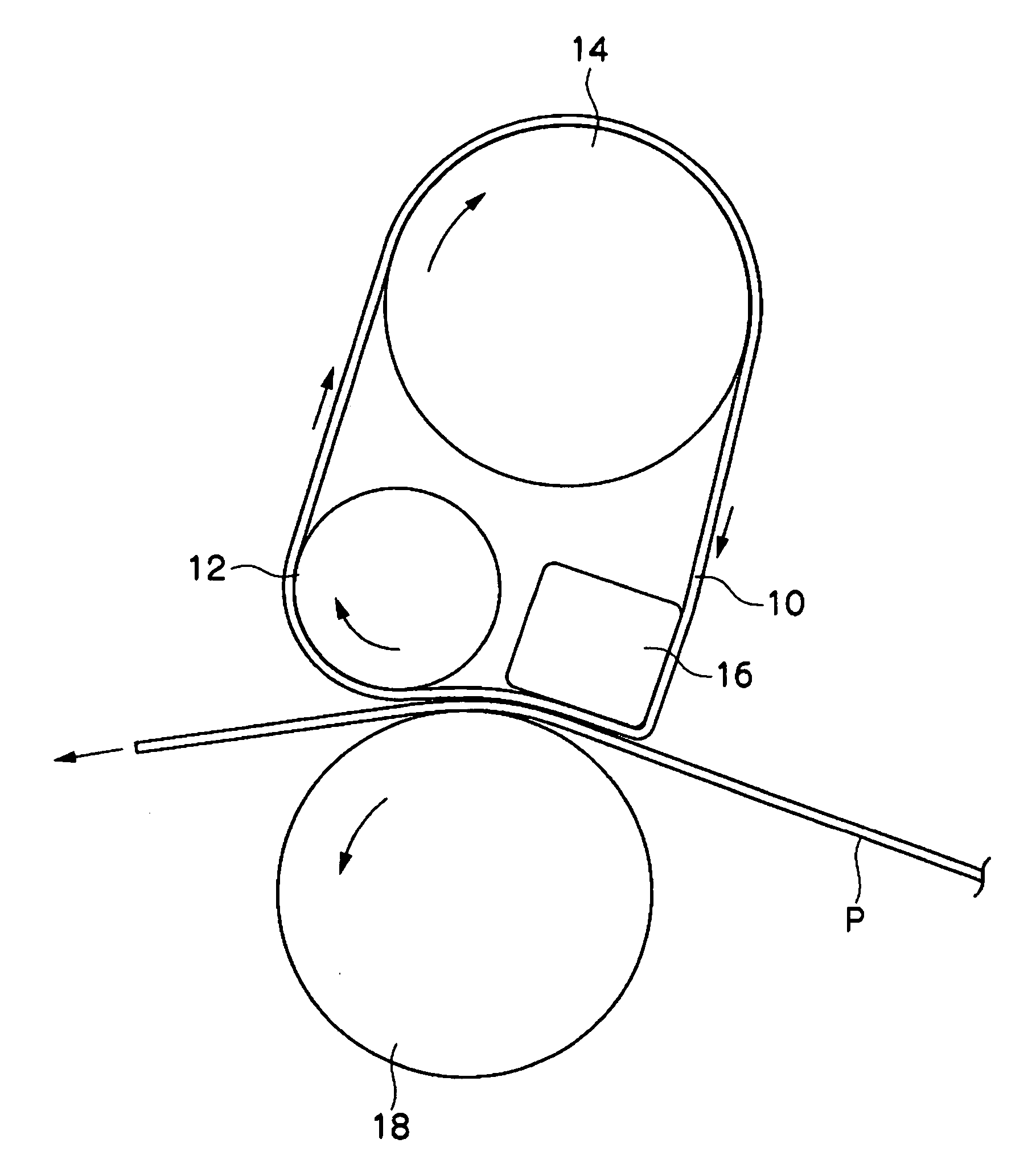
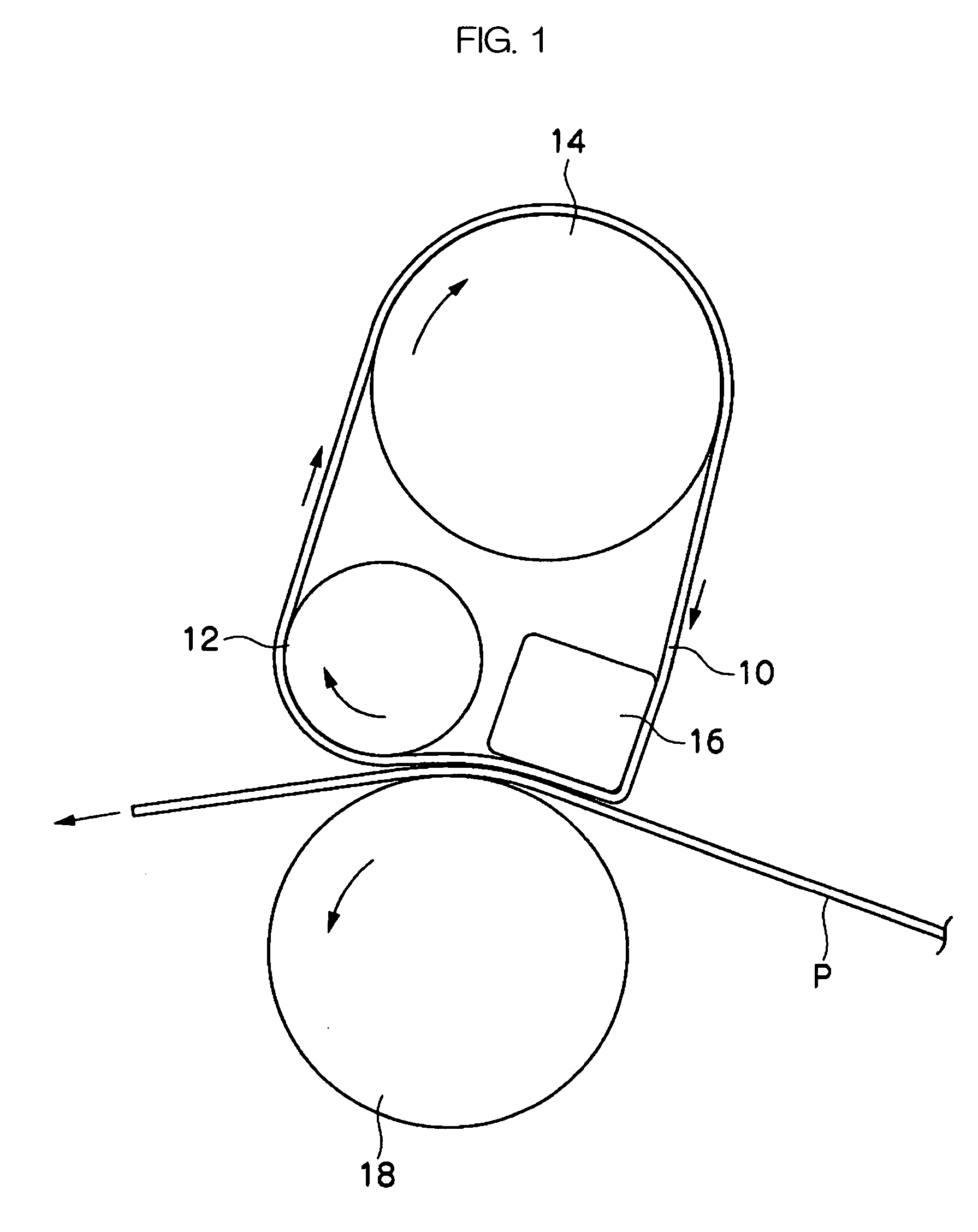
[0014] The invention makes it possible to form an image having a stable high glossiness for over a long period by employing a fixation method which causes little heat transmission and conducts thermal fixation of a toner image on a transfer body by using a heating body installed in a fixed manner for heating the transfer body, and a pressurizing member which faces the heating body via a film-like member and which is brought into contact with the heating body with pressure and rotated so as to press-contact the transfer body to the heating body, as well as by controlling the dynamic visco-elasticity of the toner.
[0015] According to the invention, it is also made possible to provide a color image formation method capable of forming an image having a stable high glossiness for over a long period and with suppression of excess thermal energy supply, and a production method of a color toner usable for the color image formation method.

Problems solved by technology

However, thermal roller fixation requires a large quantity of thermal energy when heating the roller to the above-mentioned temperature.
As a result, the temperature difference between portions of the roller contacting and not contacting the image transfer body becomes large.
However, since the non-contacting portions are also heated thereby, the temperature in the non-contacting portions further increases to possibly result in image defects known as hot-offset.
Excess thermal energy supply is also undesirable in terms of energy saving.
However, the effect is still insufficient.
Particularly, in the case of a high gloss toner, which aims at high level gloss exhibition, hot offset due to the temperature difference of the roller becomes a problem.
However, in application of a toner having high gloss in oil-less fixation, those methods cannot be said to be sufficiently effective.

Method used


Image

  • Color image forming method and color toner forming method
  • Color image forming method and color toner forming method

Examples


example 1

[0251] The developer 1 (containing the toner particles 1) is packed, the toner disposition amount is adjusted to be 15.0 g / m2 to form an image, and the fixation property is then evaluated.

[0252] In the entire temperature range and fixation speed range for the evaluation, the separation property from the fixation apparatus is found to be excellent without any resistance and offset is not at all caused. The gloss of the image is also good and a 60° mirror gloss measured in accordance with a conventionally-known method exceeds 60% in all cases.

[0253] With respect to the toner contained in the developer, the minimum value of the relaxation elasticity H in the relaxation spectrum calculated from the dynamic viscoelasticity measurement and frequency dependency according to the above-mentioned manner is 10 Pa / cm2 and the relaxation time λ is 8,200 sec. The inclination K of the frequency dispersion curve of the storage elasticity at 60° C. is 0.52.

example 2

[0254] Evaluations of the fixation property of Example 2 are conducted in the same manner as in Example 1, except that the developer 2 (containing the toner particles 2) is used in place of the developer 1.

[0255] In the entire temperature range and fixation speed range for the evaluation, the separation property from the fixation apparatus is found to be excellent without any resistance and offset is not at all caused. The gloss of the image is also good and the 60° mirror gloss exceeds 60% in all cases.

[0256] With respect to the toner contained in the developer, the minimum value of the relaxation elasticity H in the relaxation spectrum calculated from the dynamic viscoelasticity measurement and frequency dependency according to the above-mentioned manner is 890 Pa / cm2 and the relaxation time λ is 1,000 sec. The inclination K of the frequency dispersion curve of the storage elasticity at 60° C. is 0.86.

example 3

[0257] Evaluations of the fixation property of Example 3 are conducted in the same manner as in Example 1, except that the developer 3 (containing the toner particles 3) is used in place of the developer 1.

[0258] In the entire temperature range and fixation speed range for the evaluation, the separation property from the fixation apparatus is found to be excellent without any resistance and offset is not at all caused. The gloss of the image is also good and the 60° mirror gloss exceeds 60% in all cases.

[0259] With respect to the toner contained in the developer, the minimum value of the relaxation elasticity H in the relaxation spectrum calculated from the dynamic viscoelasticity measurement and frequency dependency according to the above-mentioned manner is 370 Pa / cm2 and the relaxation time λ is 2 sec. The inclination K of the frequency dispersion curve of the storage elasticity at 60° C. is 0. 13.


PUM


Abstract

The invention provides a color image forming method including charging, developing, transferring and fixing. The fixing includes thermally fixing a toner image to paper by using a heating body and a pressurizing member which is positioned opposite to the heating body via a film-like member. The color toner includes a toner particle containing a crystalline resin and a non-crystalline resin. When the color toner is subjected to dynamic viscoelasticity measurement employing a sine wave vibration method, a minimum value of the relaxation elasticity H in a relaxation spectrum obtained from frequency dispersion characteristics when a measurement frequency measured at 60 and 80° C. is 0.1 to 100 rad/sec and a measurement strain at a frequency of 6.28 rad/sec is 0.1 %, is in a range of about 10 to 900 Pa/cm2. A relaxation time λ corresponding to the minimum value is in a range of about 1 to 10,000 sec.

Description

CROSS-REFERENCE TO RELATED APPLICATION [0001] This application claims priority under 35 USC 119 from Japanese Patent Application No. 2005-162762, the disclosure of which is incorporated by reference herein. BACKGROUND OF THE INVENTION [0002] 1. Field of Invention [0003] The present invention relates to an image forming method for electrophotography and an apparatus and a developer which are used for the method. [0004] 2. Description of the Related Art [0005] Conventionally known full color development methods include, for example, a method of forming a full color image by successively developing single color toners on a photoconductor and then transferring the image to an image transfer body such as paper or an OHP film; and a method of forming a full color image by successively transferring monochromic images formed on a photoconductor to an image transfer body such as paper or a film or once transferring the images to an intermediate transfer material to form superimposed images a...

Claims


Application Information

Patent Timeline
Patent Type & Authority Applications(United States)
IPC IPC(8): G03G15/20
CPCG03G15/2064G03G2215/2016G03G15/2053G03G2215/2074G03G2215/2022
Inventor ISHIYAMA, TAKAONINOMIYA, MASANOBUNAKAZAWA, HIROSHI
Owner FUJIFILM BUSINESS INNOVATION CORP
Why Eureka
Try Eureka