Vertical fore grip with bipod

a vertical fore grip and gun handle technology, applied in the field of guns, can solve the problems of not disclosing the fore grip or gun handle of the concealable and collapsible bipod, the placement of the tripod legs on the exterior of the handle, and the severe restriction of the deployment and storage of the tripod legs

Active Publication Date: 2006-12-14
GRIP POD SYST INT
View PDF56 Cites 56 Cited by
  • Summary
  • Abstract
  • Description
  • Claims
  • Application Information

AI Technical Summary

Benefits of technology

[0012] The present invention comprises a mounting assembly that may be self-contained or may feature adaptable mounting heads to interface with Weaver or Picatinny Rail mounts or a simple bolt attachment to a firearm. A fore grip is coupled to the mounting assembly, or may be integrated with the mounting assembly, and the fore grip is to be gripped by the hand of a user when the mounting assembly is attached or coupled to a firearm. The fore grip is used for stabilizing the firearm during firing when the user grips the fore grip. A tubular recess consisting of two cylindrical cutouts is positioned within the fore grip or gun handle, and these cutouts serve as the housing for the bipod legs when concealed and as the housing for a sliding piston assembly that deploys the bipod legs.

Problems solved by technology

These patents disclose the respective art in relation to bipods, but do not disclose a fore grip or gun handle with a concealable and collapsible bipod.
Close examination of this patent reveals a number of problems with this device, and the most obvious problem is that the tripod legs are positioned on the exterior of the handle when not deployed.
If the gun with this device attached was being used in wet or muddy environments, either in a deployed or storage position, the ingress of mud and dirt into and around the handle could result in the deployment and storage of the tripod legs being severely restricted due to the mud or foreign matter.
Another problem is that deployment requires the rotation of a disengagement cam to force the legs into their deployed position and then a leg locking assembly is rotated to lock the legs into a locked position.

Method used


Image

  • Vertical fore grip with bipod
  • Vertical fore grip with bipod
  • Vertical fore grip with bipod

Examples


Embodiment Construction

[0078] Before explaining the disclosed embodiment of the present invention in detail, it is to be understood that the invention is not limited in its application to the details of the particular arrangement shown since the invention is capable of other embodiments. Also, the terminology used herein is for the purpose of description and not of limitation.

[0079] It would be useful to discuss the meanings of some words used herein and their applications before discussing the fore grip device of the present invention and method of using the same.

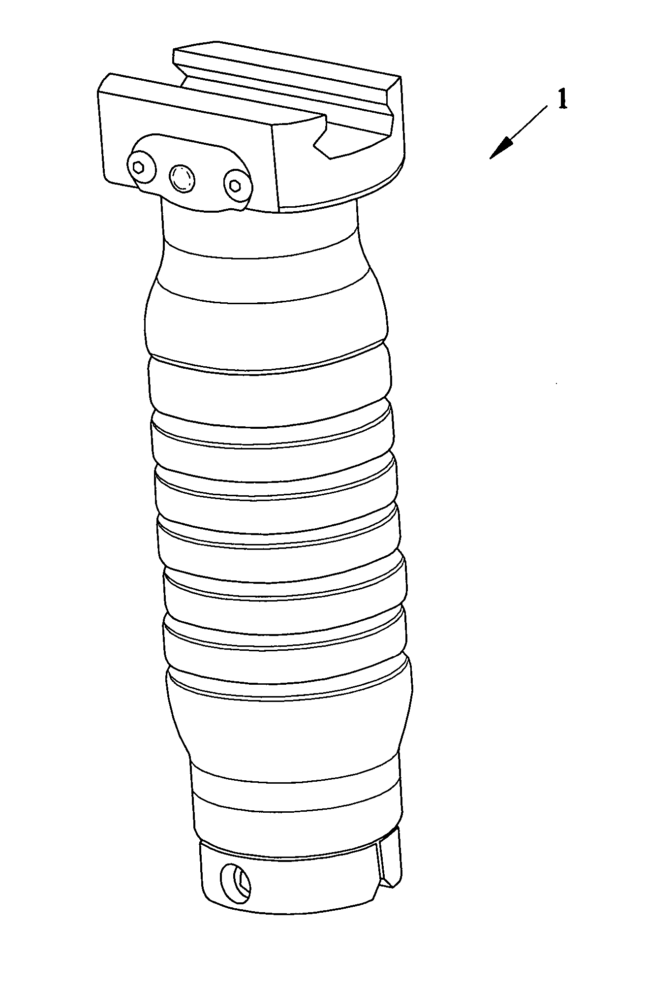
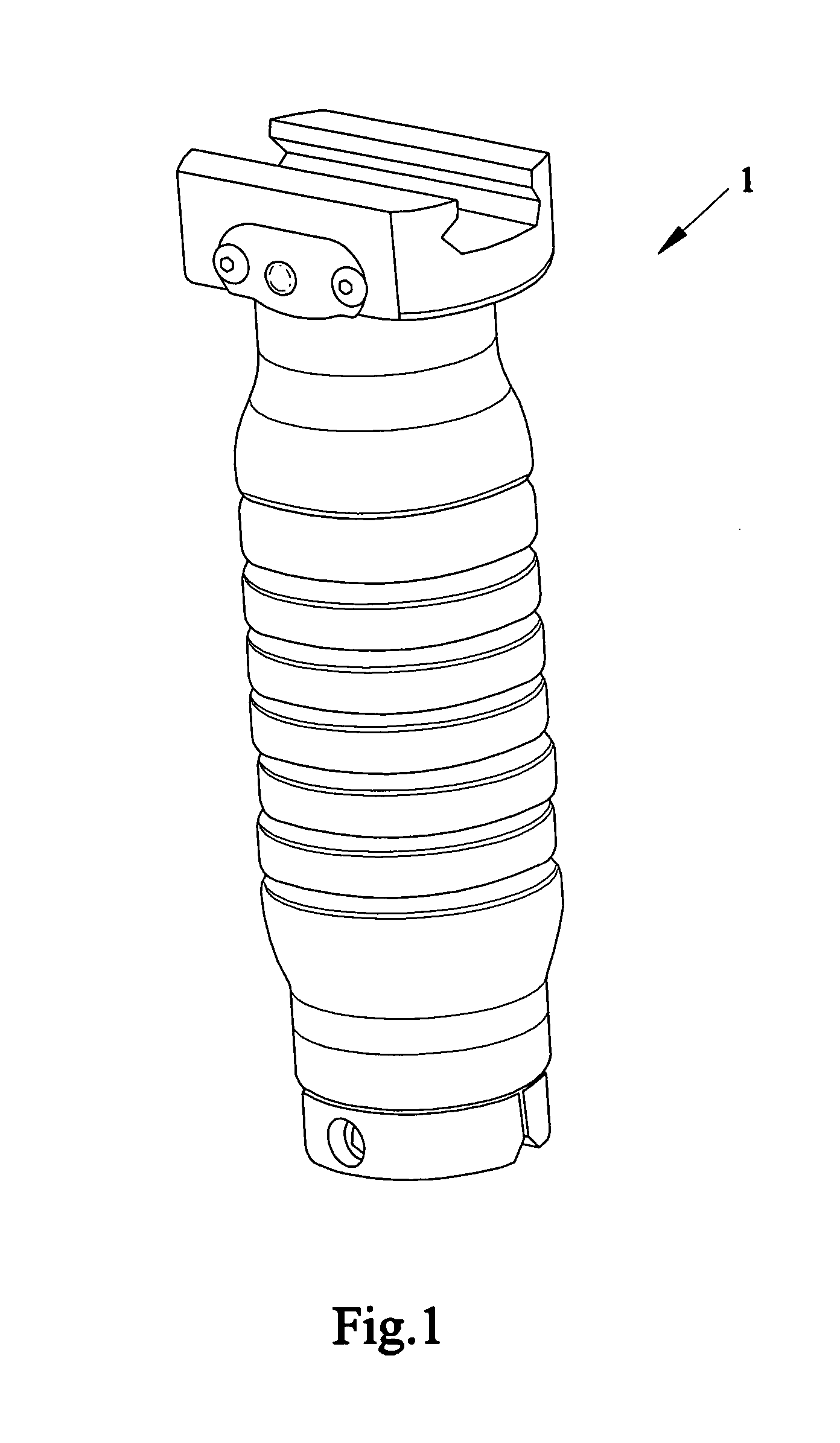
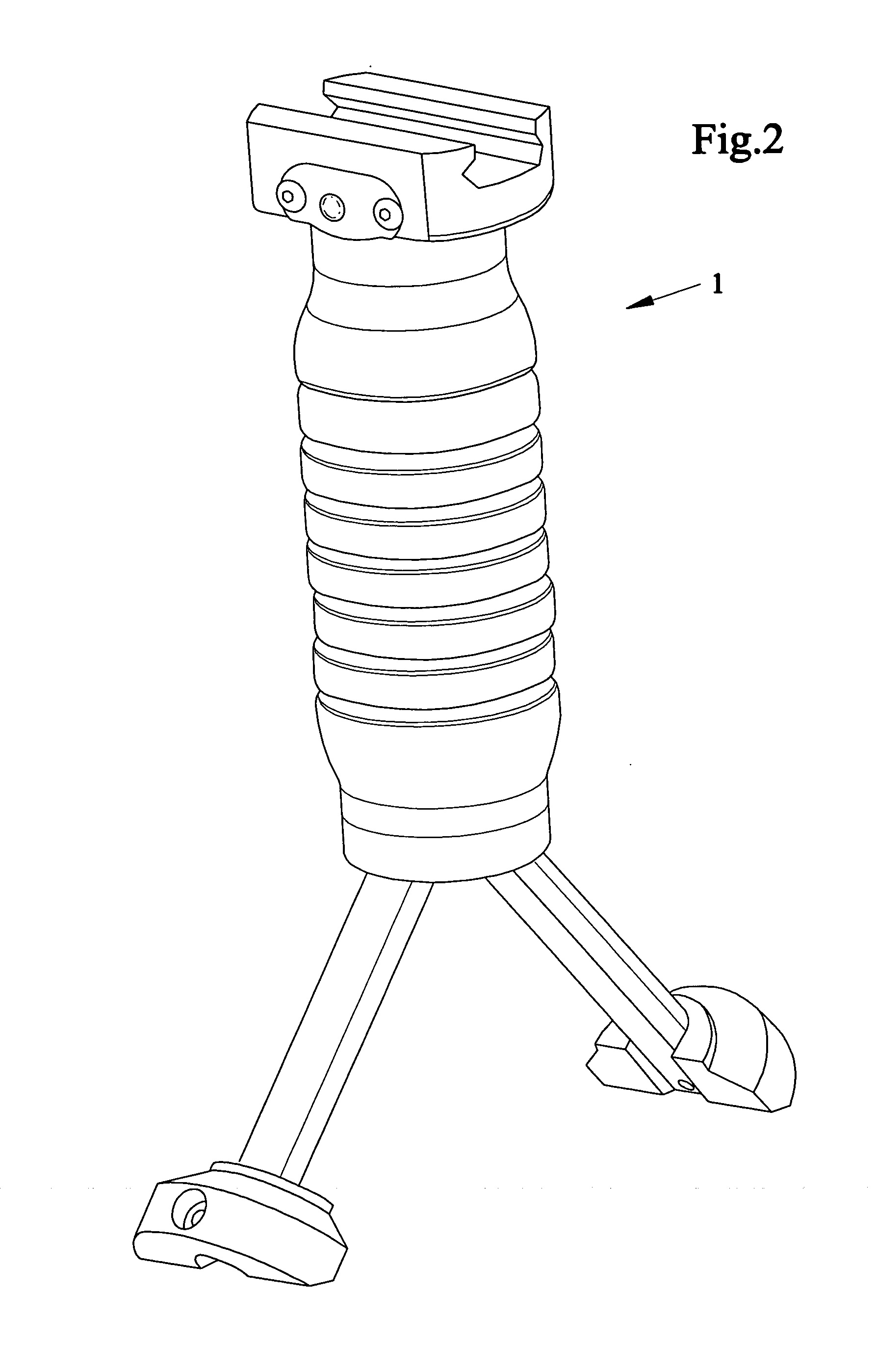
[0080] As illustrated FIGS. 1 through to 5, the fore grip 1 with concealable and collapsible bipod consists of four distinct and separate assemblies, and these are the fore grip, the piston assembly, the legs, and the release mechanism.

[0081] The fore grip consists of a fore grip with a mounting section or end 3 that is designed for attachment to a gun. The fore grip may consist of a machining or a casting that utilizes aluminum or a molding ...


PUM


Abstract

Devices, systems and methods of using an ergonomic fore grip/gun handle with a concealable and collapsible bipod. One version can have a tubular recess consisting of a first cylindrical cutout housing the bipod legs when concealed and a sliding piston that deploys the legs and a second cylindrical cutout housing a release mechanism and a void space for other accessories. The release mechanism has a compression spring positioned between the piston assembly and the bottom of the first cylindrical cutout and the compression spring. The legs are connected to the bottom of the piston assembly via a hinge and spring that when released from confinement within the fore grip, causes the legs to expand outward until fully deployed. Telescoping legs allow adjustment of leg length for use on uneven terrain. The grip portion has an outer surface with a flat surface on sides of the grip to provide a more stable grip, assist in orienting the mounted weapon and support pressure pads for lights.

Description

[0001] This invention is a continuation in part of U.S. patent application Ser. No. 10 / 725,082 filed Dec. 2, 2003, now allowed, and U.S. Design Patent Application Ser. No. 29 / 259,347 filed May 5, 2006.FIELD OF THE INVENTION [0002] The present invention relates to guns and more particularly to devices, systems and methods of using a fore grip / gun handle that combines a pistol grip and a bipod, where the bipod can be concealable and collapsible inside the pistol grip / gun handle. BACKGROUND AND PRIOR ART [0003] There has been considerable prior art for bipods, and the prior art dates back to pre-20th century times, with bipods having a familiar appearance, structure and configuration. [0004] The known prior art includes U.S. Pat. Nos. 271,251; 1,295,688; 1,355,660; 1,382,409; 1,580,406; 2,386,802; 2,420,267; 2,436,349, and 3,235,997. These patents disclose the respective art in relation to bipods, but do not disclose a fore grip or gun handle with a concealable and collapsible bipod. [...

Claims


Application Information

Patent Timeline
Patent Type & Authority Applications(United States)
IPC IPC(8): F41C23/00
CPCF41A23/08F41C23/16F41A23/10
Inventor MOODY, JOSEPH R.GADDINI, JOSEPH D.
Owner GRIP POD SYST INT
Why Eureka
Try Eureka