Structural tower

a structure and tower technology, applied in the field of structural towers, can solve the problems of increasing the height of the turbine, the cost of the larger and more massive tower, and the equipment required to erect the turbine, so as to reduce the cost of the tower, increase the power output per unit cost, and reduce the cost of energy

Inactive Publication Date: 2006-12-14
LIVINGSTON TRACY +1
View PDF55 Cites 68 Cited by
  • Summary
  • Abstract
  • Description
  • Claims
  • Application Information

AI Technical Summary

Benefits of technology

[0008] The present invention circumvents many of the difficulties previously discussed and provides for a structural tower having a more-optimal balance between structural properties—e.g., bending and torsional stiffness and damping—and weight, thereby enabling development of economically viable wind turbine farms having increased power output per unit cost. The benefits of the present invention are several, and include a reduction in the cost of energy through a reduction in the cost of the tower, transportation, and assembly. The benefits further include more efficient generation of electricity through the use of larger turbines having greater rotor lengths positioned at ever greater elevations. These benefits reduce the cost of harnessing wind energy and enable more economical wind turbine farm installations in more locations than with conventional tube towers and thereby reduce dependence on non-renewable energy sources. Each of the benefits is, moreover, realized regardless of whether the wind turbine structures are constructed, individually or in large numbers, on land or offshore at sea. Further cost reductions through use of the space frame towers of the present invention arise through elimination of the transportation bottleneck associated with conventional tube towers. The ability to use much larger capacity turbines further enhances economies of scale.
[0014] In one embodiment of the tower, one or more damping members are disposed diagonally and interconnect adjacent longitudinal members. In a second embodiment, one or more damping members are disposed longitudinally and interconnect adjacent longitudinal members. In yet a third embodiment, one or more damping members are disposed horizontally, and interconnect adjacent longitudinal or diagonal members. In yet a further embodiment, one or more damping members or, alternatively, dashpot assemblies are operably connected to amplification members, which serve to amplify small displacements in various members of the tower into relatively large displacements of the damping members or dashpot assemblies. In other embodiments, various combinations of damping members substitute for one or more of the various longitudinal, diagonal or horizontal members that comprise a structural tower having one bay or a multiple-bay, space frame construction.

Problems solved by technology

Positioning larger turbines at greater heights comes, however, with a cost.
The cost is associated with the larger and more massive towers that are required to withstand the additional weight of the larger turbines and withstand the wind loads generated by placing structures at the greater heights where wind velocities are also greater and more sustained.
An additional cost concerns the equipment that is required to erect the wind turbine.
Towers in excess of 250,000 lbs, or higher than 100 meters, however, generally require specialized and expensive cranes to assemble the tower sections and turbine.
In order to amortize the expense associated with such large cranes, wind turbine farm developers desire to pack as many wind turbines as possible onto the project footprint, thereby spreading the crane costs over many wind turbines.
However, with sites having limited footprints, developers are forced to amortize transport and assembly costs of the crane using fewer turbines, which may be economically unfeasible.
Further, projects installed on rough ground require cranes to be repeatedly assembled and disassembled, which may also be economically unfeasible.
Projects located on mountain top ridges or other logistically difficult sites may, likewise, be all but eliminated due to unfeasible economics, in addition to engineering difficulties associated with locating a crane at such sites.
The additional assembly costs, however, make this alternative unattractive.
The freight costs associated with oversize trailers and special permitting of the tower sections can exceed many tens of thousands of dollars per wind turbine.
The use of even larger rotor diameters with increasing turbine heights presents other challenges to the industry.
However, larger rotor diameters at greater heights tend to result in greater wind induced vibrations throughout the wind turbine structure and, in particular, the tower supporting the wind turbine.
The wind induced vibrations—in particular, the resonant lateral and torsional vibrations experienced in the tower—can become excessive as the turbine height approaches or exceeds 80 to 100 meters with rotor diameters exceeding 70 meters.
To control the structural problems that can arise through resonant vibrations, wind turbine designers are often forced to de-rate the turbine to lower wind speeds, limit the maximum rotor diameter or reduce the tower height.
Each of these options reduces, however, the overall economic efficiency of each wind turbine.
Because the tower mass generally increases exponentially with the tower height, however, the cost of construction also increases exponentially, thus diminishing the economic advantages sought to be obtained through positioning turbine rotors of greater length at greater heights.

Method used


Image

  • Structural tower
  • Structural tower
  • Structural tower

Examples


Embodiment Construction

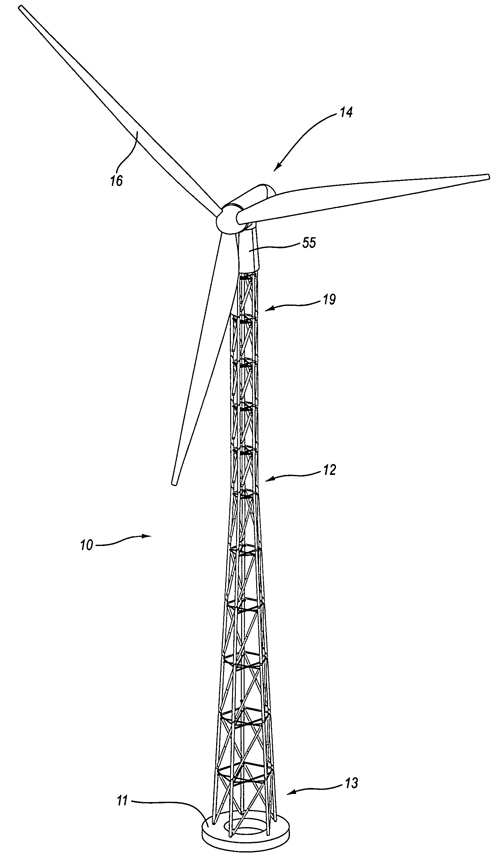
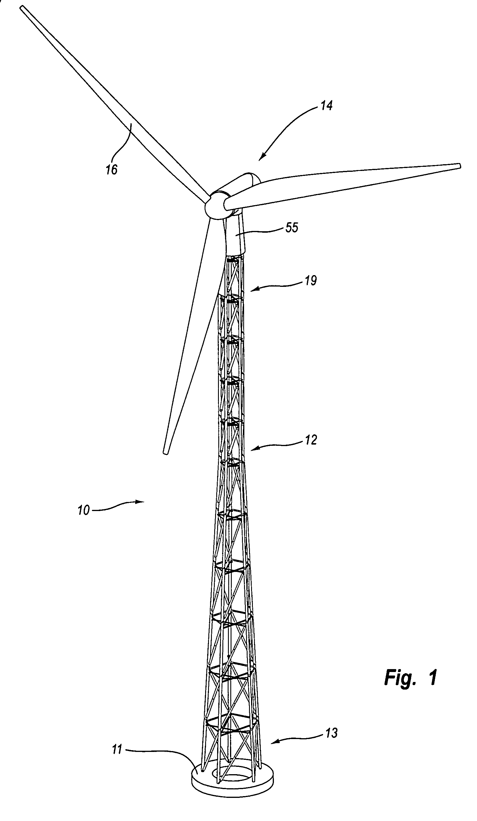
[0045] Generally, the present invention relates to a structural tower comprising a space frame that is suitable for heavy load and high elevation applications. In further detail, the present invention relates to a structural tower comprising a space frame and having damping members for damping resonant vibrations and other vibrations induced, for example, by normal wind turbine operation and in response to extreme wind loads. The present invention further relates to wind turbine applications, where the wind turbine is elevated to heights approaching eighty to one hundred meters or higher and where rotor diameters approach seventy meters or greater. Details of exemplary embodiments of the present invention are set forth below.

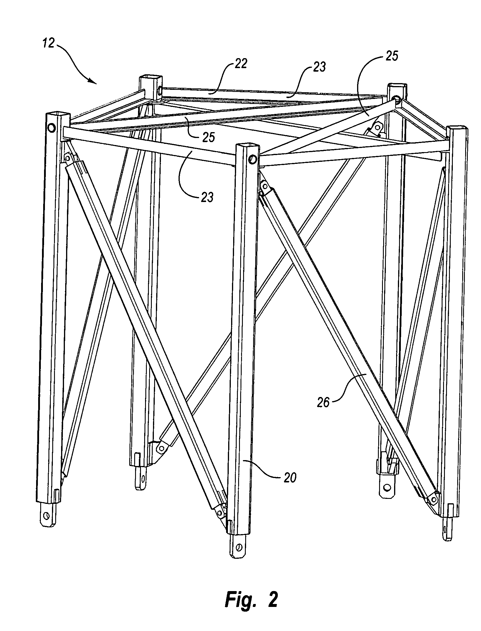
[0046]FIG. 1 illustrates a perspective view of one embodiment of a structural tower 10 of the present invention. The structural tower 10 comprises a plurality of space frame sections also commonly called bay assemblies or sections 12, 13, 19 that are assembled,...


PUM


Abstract

A structural tower having a space frame construction for high elevation and heavy load applications is disclosed, with particular application directed to wind turbines. The structural tower includes damping or non-damping struts in the longitudinal, diagonal or horizontal members of the space frame. One or more damping struts in the structural tower damp resonant vibrations or vibrations generated by non-periodic wind gusts or sustained high wind speeds. The various longitudinal and diagonal members of the structural tower may be secured by pins, bolts, flanges or welds at corresponding longitudinal or diagonal joints of the space frame.

Description

RELATED APPLICATIONS [0001] This present application claims priority to U.S. Provisional Patent Application No. 60 / 681,235, entitled “Structural Tower,” filed May 13, 2005.TECHNICAL FIELD OF THE INVENTION [0002] The present invention relates to structural towers and devices for damping vibrations in structural towers, with specific application to structural towers for wind turbines. BACKGROUND OF THE INVENTION [0003] Wind turbines are an increasingly popular source of energy in the United States and Europe and in many other countries around the globe. In order to realize scale efficiencies in capturing energy from the wind, developers are erecting wind turbine farms having increasing numbers of wind turbines with larger turbines positioned at greater heights. In large wind turbine farm projects, for example, developers typically utilize twenty-five or more wind turbines having turbines on the order of 1.2 MW positioned at fifty meters or higher. These numbers provide scale efficienc...

Claims


Application Information

Patent Timeline
Patent Type & Authority Applications(United States)
IPC IPC(8): H01Q1/08
CPCE04H12/10F03D1/001F03D11/04Y02E10/728F05B2240/9121F05B2260/30F05B2260/301F05B2230/232E02B17/0004E02B17/027E02B2017/006E02B2017/0091F03D13/10F03D13/20Y02E10/72Y02P70/50
Inventor LIVINGSTON, TRACYANDERSEN, TODD
Owner LIVINGSTON TRACY
Why Eureka
Try Eureka