Gas governor, snatch grip, and link pin for paintball gun

a paintball gun and gas governor technology, applied in the direction of compressed gas guns, white arms/cold weapons, butts, etc., can solve the problems of increased maintenance, heavy guns, and increased force required to drive the hammer mechanism backwards, so as to increase the efficiency of the marker

Inactive Publication Date: 2006-12-14
KEE ACTION SPORTS I
View PDF19 Cites 25 Cited by
  • Summary
  • Abstract
  • Description
  • Claims
  • Application Information

AI Technical Summary

Benefits of technology

[0008] The current invention addresses these needs. The main advantage is that the inventive inline cylinder includes a gas governor that reduces gas flow from a compressed gas source to a valve area when the bolt is in a firing position; this increases efficiency in the marker because only the required air is used to fire the paintball. This particular design operates independent of the valve pin, which increases cycle speed and enables the governor to open and close at the optimum time in the firing cycle. Further, when the bolt / piston is recocking, the gap between the valve pin and governor valve pin enables low pressure gas driving the piston to start pressurizing the cylinder and driving the piston rearwards without resistance from the high pressure gas.

Problems solved by technology

This design, however, has many problems, including increased maintenance, damage after repeated cycles, and a higher amount of force is required to drive the hammer mechanism backwards to be seated on the sear.
Also, because the sear and resulting hammer must be made of extremely hard materials, the gun is heavy.
Such weight is a disadvantage in paintball, where a player's agility works to his advantage.
A further disadvantage is that adjusting this pneumatic circuit can be difficult, because the same pressure of gas is used on both sides of the piston and there is no compensation for adjusting the amount of recock gas, used to drive it backwards, and the amount of velocity gas, which is the amount of force used to drive it forward and strike the valve.
This results in erratic velocities, inconsistencies, and shoot-down.
In addition, this technology often results in slower cycling times, as three independent operations must take place.
Existing spool valve designs have drawbacks as well.
In the rugged conditions of compressed gas gun use, these precise parameters are often not possible.
In addition, adjusting the velocity of a compressed gas gun becomes very difficult, because varying the gas pressure that launches a paintball in turn varies the pressure in the pneumatic cylinder, which causes erratic cycling.

Method used


Image

  • Gas governor, snatch grip, and link pin for paintball gun
  • Gas governor, snatch grip, and link pin for paintball gun
  • Gas governor, snatch grip, and link pin for paintball gun

Examples


Embodiment Construction

)

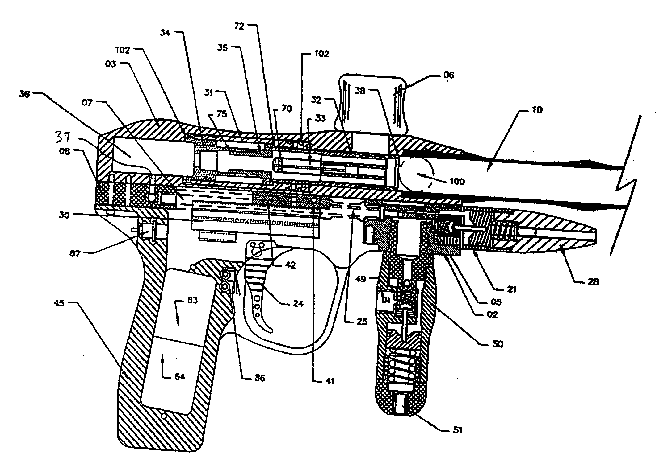
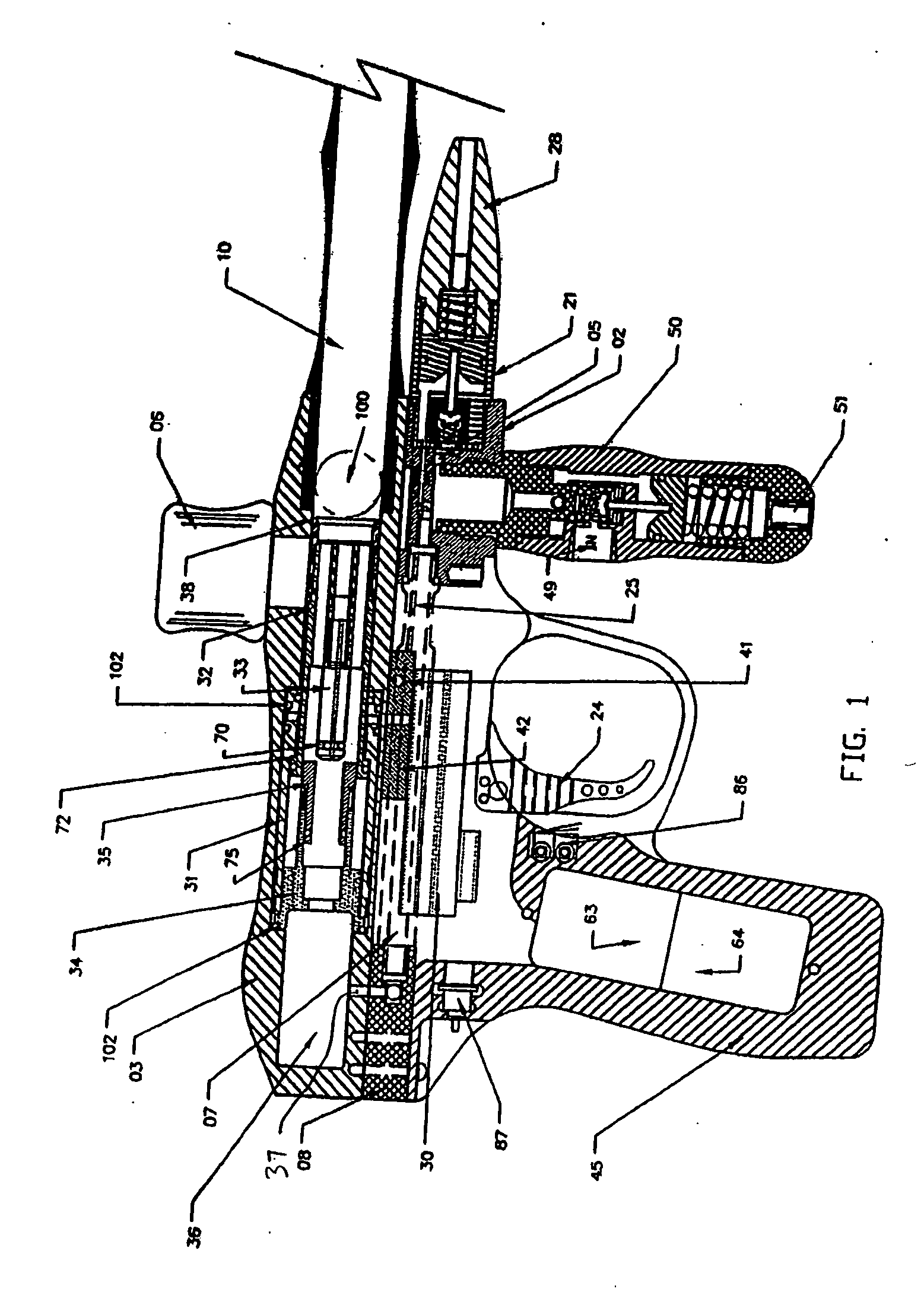
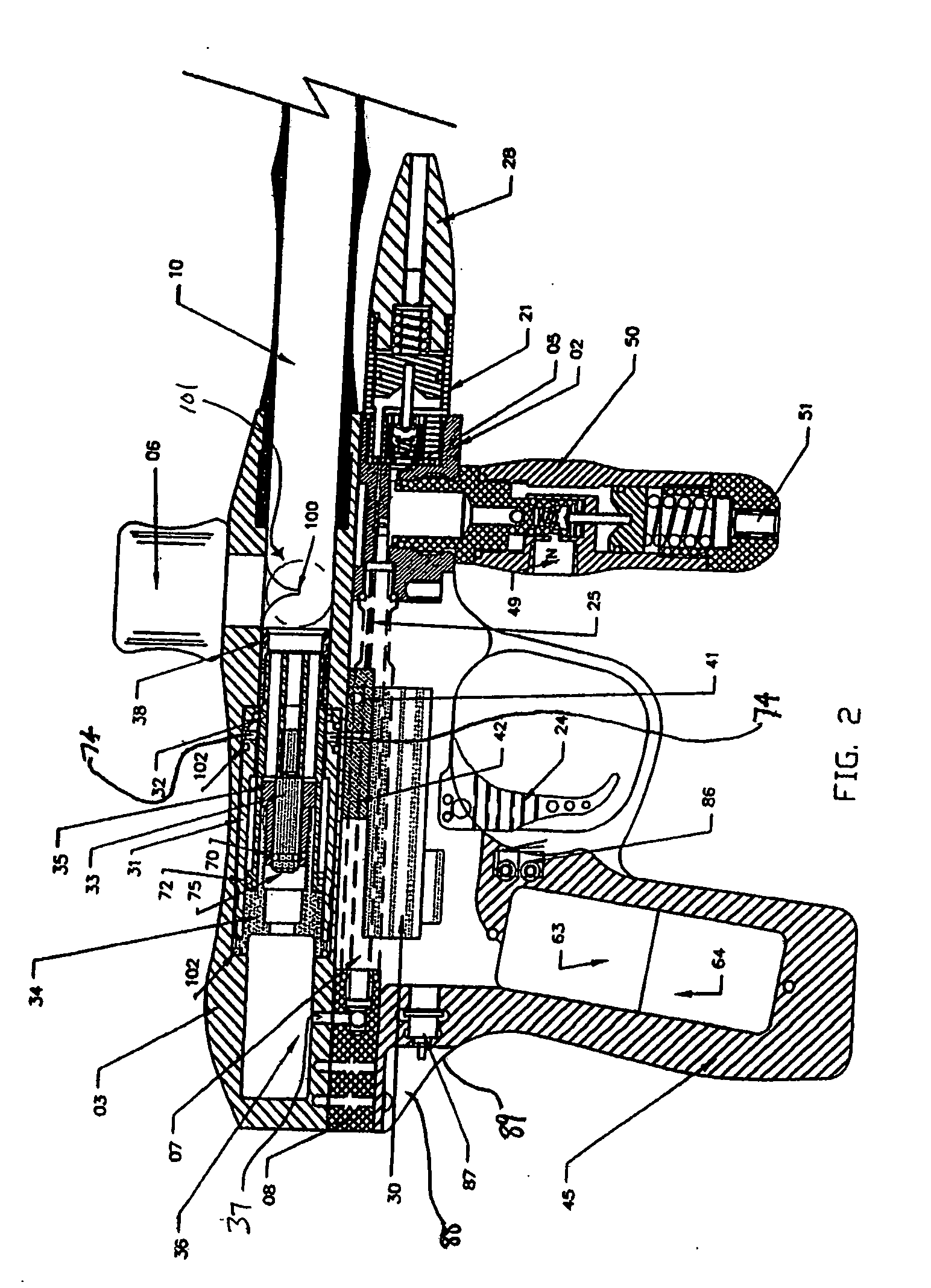
[0023]FIGS. 1-5 illustrate of a compressed gas gun incorporating a pneumatic sear. Referring to FIGS. 1 and 2, a paintball gun generally comprises a main body 3, a grip portion 45, a trigger 24, a feed tube 6, and a barrel 10. These components are generally constructed out of metal, plastic, or a suitable substance that provides the desired rigidity of these components. Main body 3 generally is connected to a supply of projectiles by feed tube 6 as understood by those skilled in the art. Main body 3 is also connected to grip portion 45, which houses the trigger 24, battery 64 and circuit board 63. The trigger 24 is operated by manual depression, which actuates micro-switch 86 directly behind trigger 24 to send an electrical signal to circuit board 63 to initiate the firing or launching sequence. Barrel 10 is also connected to body 3, preferably directly in front of feed tube 6, to allow a projectile to be fired from the gun.

[0024] Hereinafter, the term forward shall indicate being...


PUM


Abstract

A paintball marker has an inline cylinder that includes a gas governor that reduces gas flow from a compressed gas source to a valve area when the bolt is in a firing position; this increases efficiency in the marker because only the required air is used to fire the paintball. This bolt operates independent of the valve pin, which increases cycle speed and enables the governor to open and close at an optimum time in the firing cycle. Further, when the bolt/piston is recocking, the gap between the valve pin and governor valve pin enables low pressure gas driving the piston to start pressurizing the cylinder and driving the piston rearwards without resistance from the high pressure gas. The marker also allows a user to remove the inline cylinder without the use of tools, and gives the user a convenient carrying handle for holding the paintball marker, which is commonly called a “snatch grip.”

Description

CROSS REFERENCE TO RELATED APPLICATIONS [0001] This application is a continuation-in-part of U.S. patent application Ser. No. 11 / 183,548, filed Jul. 18, 2005, which claims the benefit of U.S. Provisional Nos. 60 / 588,912 and 60 / 654,262 filed Jul. 16, 2004 and Feb. 18, 2005 respectively, and also claims the benefit of U.S. Provisional No. 60 / 654,120 filed Feb. 18, 2005, which are incorporated by reference as if fully set forth.BACKGROUND OF THE INVENTION [0002] This invention relates generally to the construction of compressed gas guns and more particularly to the guns designed to propel a liquid containing frangible projectile, otherwise known as a “paintball.” As used herein, the term “compressed gas” refers to any mean known in the art for providing a fluid for firing a projectile from a compressed gas gun, such as a CO2 tank, a nitrous tank, or any other means supplying gas under pressure. Older existing compressed gas guns generally use a mechanical sear interface to link the tri...

Claims


Application Information

Patent Timeline
Patent Type & Authority Applications(United States)
IPC IPC(8): F41B11/00F41B11/62
CPCF41A19/12F41B11/62F41B11/71F41B11/721F41C23/16
Inventor DOBBINS, JERROLD M.DOBBINS, GERALD
Owner KEE ACTION SPORTS I
Why Eureka
Try Eureka